Fig. 1 – Crompton Controls M20 User Manual
Page 13
12
Wiring
Emotron AB 01-2551-01r4
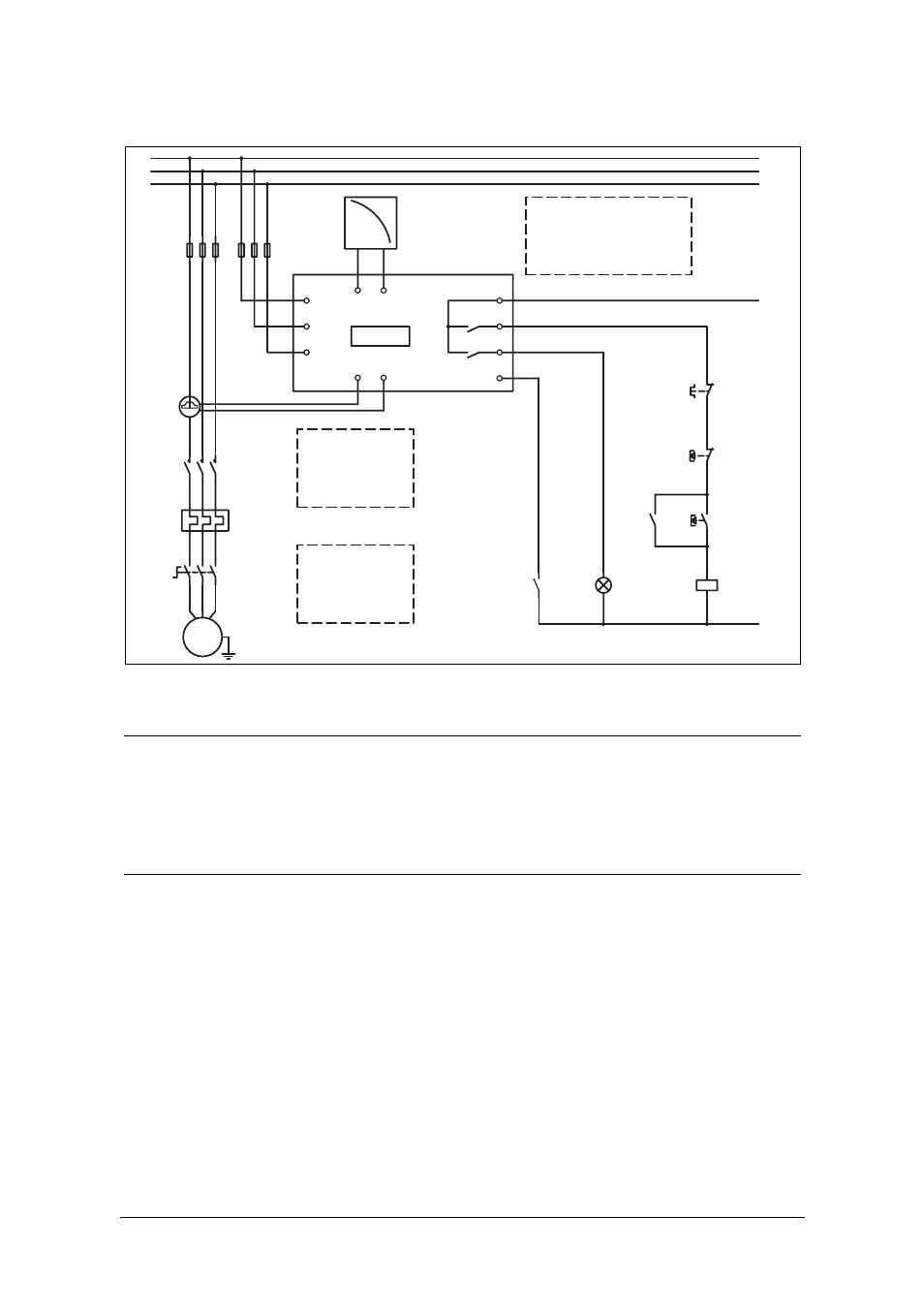
Fig. 1
Connection example
Please use the enclosed plastic (rubber) insert (if ordered, optional) to cover the
monitor terminals.
NOTE: If the START/STOP is connected as per Fig. 1, it is recommended that
terminals 6 and 7 be bypassed during programming. After the programming
is completed the bypass must be taken out. Make sure that the monitor
voltage range e.g. 3x380-500 VAC matches the connected motor/line
voltage, e.g. 3x 400 V.
M20
A+
A-
R1
R2
C
L1
L3
L2
S2
S1
DIG
{
L1
L2
L3
K1
U
V
W
M
K1
K1
3
4
9
11
13
1
2
6
7
8
5
CTMxxx
NOTE: In power
down, both relays
are always N.O.
-Reset
-Auto set
- Block
PRE-
ALARM
NOTE: Monitor
voltage see
Note below.
N (alt. 48 VDC+)
Max. 240 VAC (alt. 0 VDC-)
Please see CTM
information
on Page 11.
Stop
Start