2 automatic calibration check of the microphone – Casella CEL CEL-450 User Manual
Page 38
DO NOT remove the protective metal grid from Class
1 microphones.
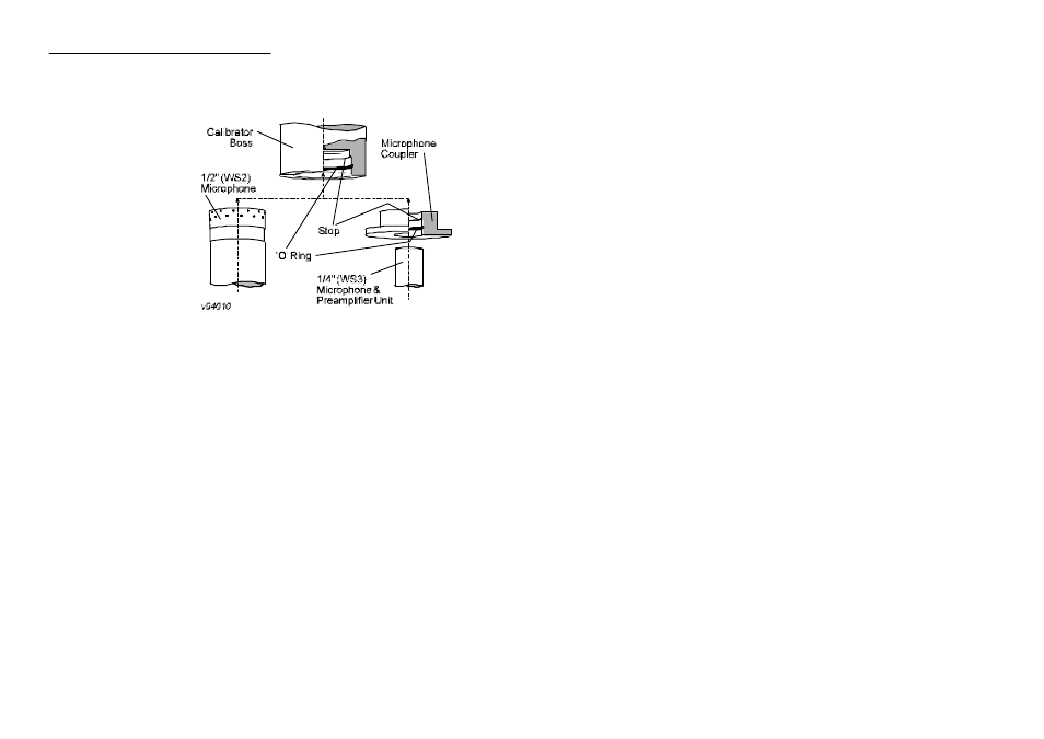
With a WS2, 1/2"
microphone, fit the
calibrator directly on to
the microphone, making
sure it is pushed firmly
into contact with the stop
in the calibrator cavity
(Figure 5).
With a WS3, 1/4"
microphone, fit the
coupler, supplied with
the calibrator, on to the
microphone making sure
it is pushed firmly into
contact with the stop in
the coupler cavity (Figure 5). Then fit the coupler complete with
microphone and instrument into the calibrator cavity, again ensuring that
it is pushed firmly into contact with the stop in the calibrator cavity.
DO NOT lay the sound level meter and calibrator on a
horizontal surface during calibration, as the combined
weight will cause the microphone to move inside the
calibrator cavity with the risk of causing damage and the
possibility of obtaining an incorrect calibration level.
Support the sound level meter and calibrator in an upright
position. To aid removal, the coupler flange does not fit tightly against
the calibrator housing.
A Calibration screen is displayed at the end of the start up
sequence and this will be the normal entry to the calibration check. The
Calibration screen can also be obtained via the Calibration option on the
Main menu. Perform an automatic calibration check of the microphone
as detailed in Section 4.2, or a manual check as described in Section 4.3
4.2 Automatic Calibration Check of the
Microphone
The Calibration screen shown after start up allows automatic calibration.
Figure 5: Fitting the acoustic calibrator
Page 38 - CEL-450/490 Operators Handbook
Acoustic Calibration Check