Figure 2–2, Step 3: interpret the results, Step 4: fixing the problem – Altera Early SSN Estimator User Manual
Page 12
2–2
Chapter 2: Tutorial: Mixing SSTL and LVTTL in a Single Bank
Early SSN Estimator User Guide for Altera Programmable Devices
© November 2009
Altera Corporation
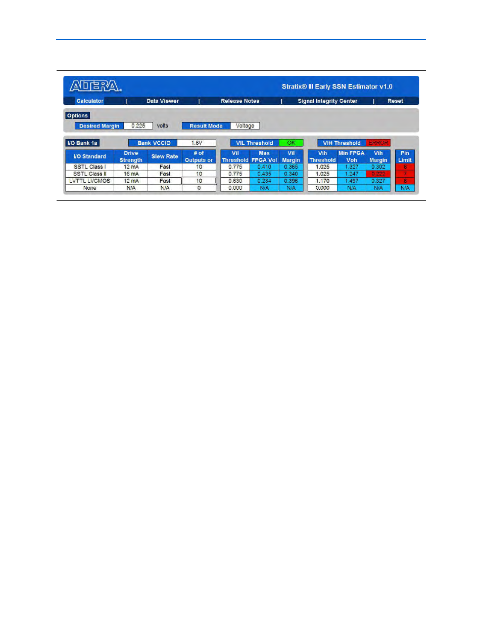
Step 3: Interpret the Results
■
The V
IH
threshold indicator is red, indicating that a margin has been violated.
■
The V
IH
margin for SSTL Class II is 0.222 V (less than the 0.225 V that you want for
your design). This is highlighted in red to indicate that it is lower than the desired
margin.
■
The pin limit for SSTL Class II is seven pins. This means that if the number of
outputs for SSTL Class II is reduced to seven, the margin will no longer be
violated.
■
The pin limit for LVTTL is eight pins. This means that only eight LVTTL pins can
be safely combined with ten SSTL Class I and ten SSTL Class II pins under the
entered drive strengths and slew rate for the given desired margin of 0.225 V that
you set.
Step 4: Fixing the Problem
There are multiple approaches to fix the issue.
First Approach
Reduce the amount of margin that you want to allocate for non-SSN-related items
from 225 mV to 200 mV, as shown in
.
The pin limit for LVTTL increased from 8 to 22, thereby allowing you to implement
your design with ten SSTL Class I I/Os and ten SSTL Class II I/Os, along with ten
LVTTL output pins.
Figure 2–2. Local Parameters Assignment