Altera Device-Specific Power Delivery Network User Manual
Page 24
1–20
Chapter 1: User Guide for the Device-Specific Power Delivery Network (PDN) Tool
Design PCB Decoupling Using the PDN Tool
Device-Specific Power Delivery Network (PDN) Tool User Guide
September 2012
Altera Corporation
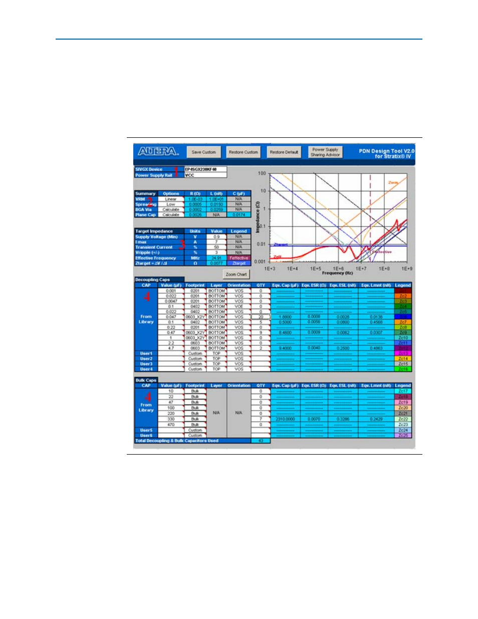
2. Select the parameter setting for the PDN components.
3. Enter the electric parameters to set Z
TARGET
and F
EFFECTIVE.
4. Derive the PCB decoupling scheme.
The red numbers in
show the field to work with in each of these steps. For
more information on these fields, refer to
“Decap Selection” on page 1–13
In Step 2, the PDN tool uses the inductance and resistance value calculated in the
BGA Via
tab if you choose the Calculate option for the BGA via. Incorrect parameters
may negatively affect the derived decoupling design. These values are calculated
using the parameters you entered in the BGA Via tab. You must check the BGA Via
tab to ensure the numbers you entered—especially the number and length of the BGA
power via pair—matches the settings of the power rail selected in Step 1.
Figure 1–15. Decap Selection Tab in a Single-Rail Design