Byteblaster ii 10-pin header connection, Byteblaster ii 10-pin header connection –3 – Altera ByteBlaster II User Manual
Page 19
Chapter 2: ByteBlaster II Specifications
2–3
ByteBlaster II Connections
© July 2008
Altera Corporation
ByteBlaster II Download Cable User Guide
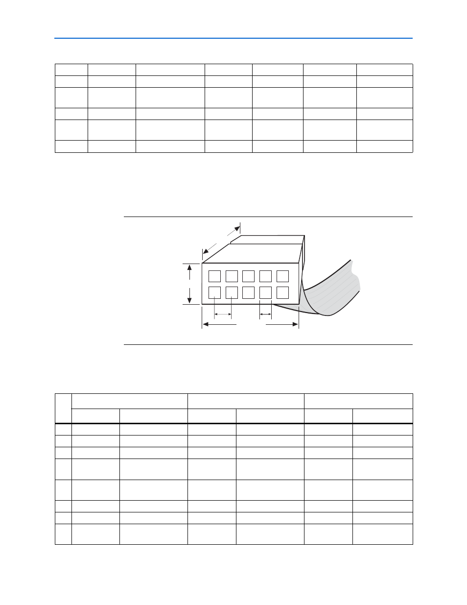
ByteBlaster II 10-Pin Header Connection
The 10-pin female plug connects to a 10-pin male header on the circuit board.
shows the dimensions of the female plug.
identifies the 10-pin female plug signal names and the corresponding
programming mode.
5
nCE
Cyclone chip enable
—
No connect
—
No connect
8
ASDI
Active serial data in
DATA0
Data to device
TDI
Data to device
11
CONF_DONE
Configuration done
CONF_DONE
Configuration
done
TDO
Data from device
13
DATAOUT
Active serial data out
nSTATUS
Signal status
—
No connect
15
nVCC
Detect
—
nVCC
Detect
—
nVCC
Detect
—
18 to 25
GND
Signal ground
GND
Signal ground
GND
Signal ground
Table 2–2. ByteBlaster II 25-Pin Header Pin-Outs
(Part 2 of 2)
Figure 2–2. ByteBlaster II 10-Pin Female Plug Dimensions
0.250 Typ.
0.700 Typ.
0.425 Typ.
0.100 Sq.
10
9
8
7
6
5
4
3
2
1
0.025 Sq.
Dimensions are shown in inches. Spacing between pin centers is 0.1 inches.
Table 2–3. ByteBlaster II Female Plug Signal Names and Programming Modes
(Part 1 of 2)
Pin
AS Mode
PS Mode
JTAG Mode
Signal Name
Description
Signal Name
Description
Signal Name
Description
1
DCLK
Clock signal
DCLK
Clock signal
TCK
Clock signal
2
GND
Signal ground
GND
Signal ground
GND
Signal ground
3
CONF_DONE
Configuration done
CONF_DONE
Configuration done
TDO
Data from device
4
VCC(TRGT)
Target power supply
VCC(TRGT)
Target power supply
VCC(TRGT)
Target power
supply
5
nCONFIG
Configuration control
nCONFIG
Configuration control
TMS
JTAG state
machine control
6
nCE
Cyclone chip enable
—
No connect
—
No connect
7
DATAOUT
Active serial data out
nSTATUS
Configuration status
—
No connect
8
nCS
Serial configuration
device chip select
—
No connect
—
No connect