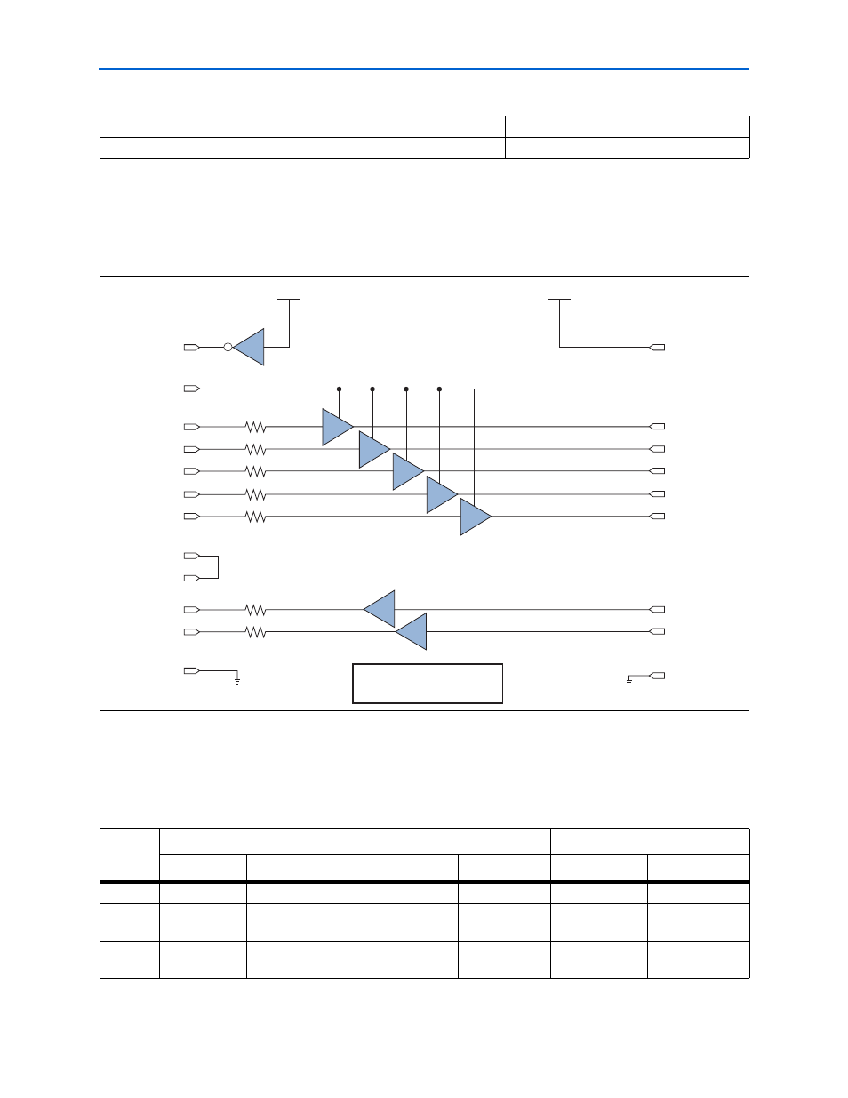
Cable-to-board connection, Byteblaster ii 25-pin header connection, Figure 2–1: byteblaster ii block diagram -2 – Altera ByteBlaster II User Manual
Page 18
2–2
Chapter 2: ByteBlaster II Specifications
ByteBlaster II Connections
ByteBlaster II Download Cable User Guide
© July 2008
Altera Corporation
Cable-to-Board Connection
The ByteBlaster II cable has a standard parallel printer plug that connects to the PC.
shows a block diagram of the ByteBlaster II download cable.
ByteBlaster II 25-Pin Header Connection
The 25-pin male header connects to a parallel port with a standard parallel cable.
identifies the plug pin names and the corresponding programming modes.
EPC4, EPC8, and EPC16 devices
3.3 V
EPCS1, EPCS4, EPCS16, EPCS64, and EPCS128 devices
3.3 V
Table 2–1. ByteBlaster II V
CC(TRGT)
Pin Voltage Requirements
(Part 2 of 2)
Figure 2–1. ByteBlaster II Block Diagram
15
VCC
4
VCC
14
TRI
TRI
TRI
TRI
TRI
2
3
4
5
8
1
5
8
6
9
11
13
6
10
3
7
18 to 25
Series Resistors for Signal Quality
and Parallel Port Protection
(Typically 100
Ω)
GND
2, 10
GND
Table 2–2. ByteBlaster II 25-Pin Header Pin-Outs
(Part 1 of 2)
Pin
AS Mode
PS Mode
JTAG Mode
Signal Name
Description
Signal Name
Description
Signal Name
Description
2
DCLK
Clock signal
DCLK
Clock signal
TCK
Clock signal
3
nCONFIG
Configuration control
nCONFIG
Configuration
control
TMS
JTAG state
machine control
4
nCS
Serial configuration
device chip select
—
No connect
—
No connect