Figure 1–2: hardware setup dialog box -6, Table 1–1: programming modes -6 – Altera ByteBlaster II User Manual
Page 14
1–6
Chapter 1: Setting Up the ByteBlaster II Download Cable
Software Setup
ByteBlaster II Download Cable User Guide
© July 2008
Altera Corporation
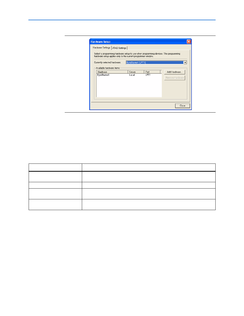
7. Click Close to close the Hardware Setup dialog box.
8. In the Mode list, select the desired mode (Programmer window).
describes each mode.
1
The ByteBlaster II supports the Joint Test Action Group (JTAG), Passive
Serial Programming, and Active Serial modes.
f
For details about the Quartus II Programmer, re
chapter in volume 1 of the Quartus II Handbook.
f
For details about programming devices and creating secondary programming files,
refer to the Programming & Configuration
f
For more information, refer to the Programming module of the Quartus II software
online tutorial and the following topics in the Quartus II Help:
■
Changing the Hardware Setup
■
Programmer Introduction
■
Overview: Working with Chain Description Files
Figure 1–2. Hardware Setup Dialog Box
Table 1–1. Programming Modes
Mode
Mode Description
Joint Test Action Group (JTAG)
Programs or configures all Altera devices supported by the Quartus II software,
excluding FLEX 6000 and EPCS serial configuration devices.
In-Socket Programming
Not supported by the ByteBlaster II cable.
Passive Serial Programming
Configures all Altera devices supported by the Quartus II software, excluding MAX
3000, MAX 7000, MAX II, and EPCS serial configuration devices.
Active Serial Programming
Programs a single EPCS1, EPCS4, EPCS16, EPCS64 or EPCS128 serial configuration
device.