Parameter setup (continued...) – Nexen TM340 912751 User Manual
Page 13
10
FORM NO. L21279-B-0513
5. PARAMETER SETUP (continued...)
5.4
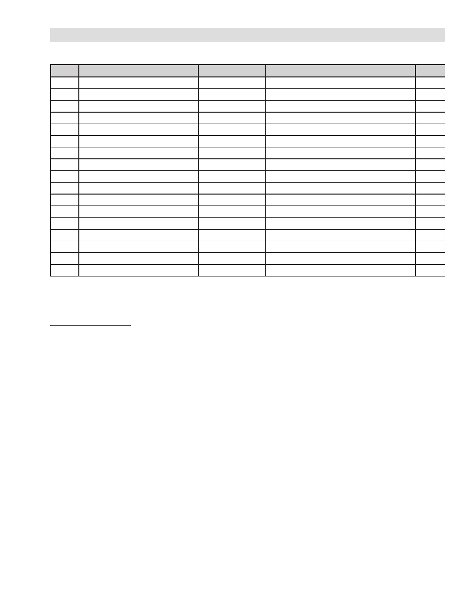
PARAMETER LIST
5.5 PARAMETER DESCRIPTIONS
Calibration Parameters
The following parameters are used to adjust the tension display, full scale tension, and calibration of the unit. It is
recommended to refer to Section 5.3 for instructions on the calibration procedure.
Code Function Description
Default Value
Set Range
Unit
0
Tension sensor selection
0 0–6, 10–17*
0
1
Tension display decimal point selection
0 0, 0.0, 0.00
0
2
Tension full scale setting
* 1.00g19.90, 10.0g199.0, 100g2000
x 10N
3
Display filter selection
1500 300, 600, 1000, 1500, 2000
msec
4
Control output filter selection
10 10, 20, 40, 60, 80, 100, 200, 500
msec
5
Control output type selection
0~10 0–5V, 0–10V, 4–20mA
V or mA
6
Meter output filter selection
500 50, 100, 200, 500, 1000, 1500, 2000
msec
7
Indicator output filter selection
1000 800, 1000, 1500, 2000
msec
8
Minimum tension alarm setting
0 0 g Full Scale
x 10N
9
Maximum/Unbalanced alarm selection
0 0, 1
A
Maximum tension alarm setting
Full Scale 0 g Full Scale
x 10N
Unbalanced alarm setting
10 0 g Full Scalle
x10N
B
Automatic tare adjustment
C
Automatic span adjustment
* 10% g Full Scale
x 10N
D
Output Scaling
100 50 g150
%
E
Display/Hide alarm setting
0 0, 1
F
Equipment number
1 1 ~ 99
0: Tension Sensor Selection
Sets the type of sensor used. See Section 5.3 for
details.
1: Decimal Placement
Set the location of decimal place. Select between 0,
0.0, 0.00. Must be set before calibration. Limits the full
scale range that can be set in Parameter 2. Changing
setting will require calibration to be performed.
2: Full Scale Tension
Sets the full scale value for tension. Can be set in the
range of 1 – 2,000. The range and number of digits is
limited by selection in Parameter 1.
5: Control Output Selection
Select the control output type.
Selectable values: 0—5V, 0—10V, 4—20mA.
NOTE: Only one output terminal, corresponding
to the selected output type should be wired to
equipment.
B: Tare Adjustment
Performs tare adjustment of load cell calibration. See
Section 5.3 for procedural details.
C: Span Adjustment
Performs span adjustment of load cell calibration. See
Section 5.3 for procedural details.
D: Output Scaling
Sets the scaling of the control output signal, normally
set to 100%. This setting will not affect the upper limit
(voltage or current) of the output.
Selectable range: 50–150%
* Not all selections are valid for setup. See Section 5.3 for details.