Nexen TM340 912751 User Manual
Page 11
8
FORM NO. L21279-B-0513
5. PARAMETER SETUP
5.1
NAVIGATING SETUP MODE
The tension meter is setup using parameters described in Section 5.4. To enter setup mode, press and hold the P button
until the display changes to read 0 in the first column.
Once in setup mode, use the keys to navigate:
Press P: Exit setup mode
Press S: Cycle digits to edit when entering a number. The selected digit will blink.
Press
r
/
s
: Increase/Decrease the select digit, or cycle through parameter options.
Hold S and Press
r
/
s
: Change parameter to Next/Previous without applying change.
Press
8
: Apply parameter change. Display will blink showing setting has been accepted, then automatically shifts
to the next parameter.
NOTE
On initial power up, when “SEtUP” is displayed, setup mode must be entered to proceed. The initial setup
will advance through a preset series of parameters to set up an initial calibration.
Continue reading to Section 5.2 Initial Setup for details on initial setup.
5.2
INITIAL SETUP
After applying power to the unit the first time, “SEtUP” will be displayed. The most basic parameters will be setup in a
fixed order to calibrate the unit initially. This initial setup must be completed before the unit will allow for the selection of
additional setup parameters. To begin the setup, hold the P button (3 seconds) until the unit enters setup mode showing
parameter 0 as the first parameter.
• The screen will display “SEtUP” again if the setup mode is exited prematurely by pressing the P button, or if the power
is switched off.
• It is not possible to select between parameters using the S + r/s button combination while performing the initial
setup. Parameters not set during the initial setup can be set after the initial setup has been completed.
5.3 CALIBRATION
During the initial setup, the following parameters will be configured in the preset order as presented in this section. To
repeat calibration after the initial setup, repeat the steps below. Ensure that parameters No. 0, 1, and 2, are adjusted if the
model of sensor has changed.
Full Scale
Parameter No. 0:
Set to the sensor type used per the table below.
Parameter No. 1:
Set the placement of the decimal point in the
tension meter display, which will also limit the
maximum tension value that can be displayed.
0:
100 ~ 2000 Full Scale
0.0:
10.0 ~ 199.0 Full Scale
0.00: 1.00 ~ 19.90 Full Scale
Parameter No. 2:
Set the full scale tension. This will be the maximum
tension that the tension meter will be calibrated for
and is the full scale value used for setting output
levels and alarm triggers.
SETTING
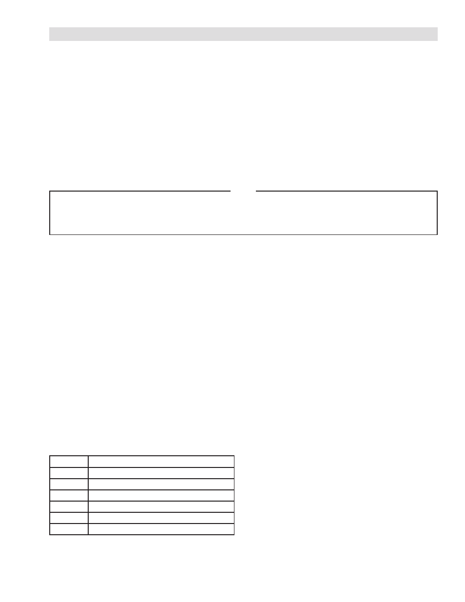
SENSOR
0
TSA010K
1
TSA200, TSA1000
2
N/A
3
MB or SW Series
4, 5, 6
N/A
10-17
Reserved for Diagnostics. Refer to Section 6.