Opgp-34-a4b3ra, Electrical interface characteristics, Transmitter burst mode timing characteristics – Delta Electronics GPON ONU Transceiver OPGP-34-A4B3RA User Manual
Page 4
OPGP-34-A4B3RA
DELTA ELECTRONICS, INC.
4 Revision:
S2
12/26/2006
www.deltaww.com
5. Electrical Interface Characteristics
Parameter
Symbol
Min.
Typ.
Max.
Unit
Note
Transmitter
Total Supply Current
I
CC
A
mA
Note
(1)
Differential line input Impedance
R
IN
80
100
120
Ohm
Differential Data Input Swing
V
DT
400 2000
mV
p-p
Data Input Voltage- High
V
IH
-V
CC
-1.165
-0.880
V
Data Input Voltage- Low
V
IL
-V
CC
-1.810
-1.475
V
LVPECL
BiasCNT Input Voltage- High
V
BCNTH
2 V
CC
BiasCNT Input Voltage- Low
V
BCNTL
0 0.8
LVTTL
Receiver
Total Supply Current
I
CC
B
mA
Note
(1)
Differential Data Output Swing
V
DR
700 900
mV
p-p
Note
(2)
Signal Detect Output Voltage-High
V
LOSH
2
V
CC
+0.3
V
Signal Detect Output Voltage-Low
V
LOSL
0 0.8 V
LVTTL
Note (1). A (TX)+ B (RX) = 350mA (Not include termination circuit)
Note (2). Internally AC coupled, but requires a 100Ohm differential termination at or internal to Serializer/
Deserializer.
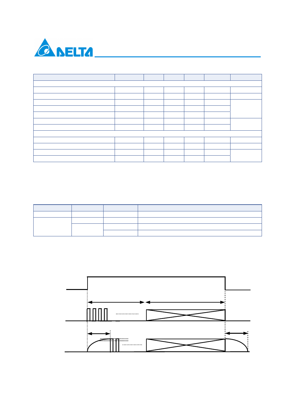
6. Transmitter Burst Mode Timing Characteristics
VccT
BiasCNT
Data Input Optical Output
VccT < 3.135V
X
X
OFF
Low X
OFF
No Other
VccT > 3.135V
High
Yes
Laser bias and modulation signal output
X = Don’t care
Other = Less than +8dBm (peak)
High = Logic high level, Low = logic low level
No = Data NOT Present, Yes = Data Present,
OFF = Optical Power is less than –45dBm
Preamble
Payload
Ton<16 bits
BiasCNT
TD (p)
Optical Output
Toff<16 bits
Tx Enable
Tx Disable
Within 15% of steady state
Ton/Toff Time Definition