Woodhaven 8250K: Portable Router Table, Fence & Leg Set User Manual
Page 2
1
MOUNT ROUTER
Follow the Router Mounting instructions included with
the Router Plate (PTM100P) for drilling and mounting the
plate to your router. Set the Table/Leg assembly on its side
and insert the four 1" screws (MF015) thru the countersunk
holes in the Table. Mount the Router Plate/router in the
recess in the underside of the Table using the 1" washers
(WFN002) and locknuts (NUT010). See fig. 3.
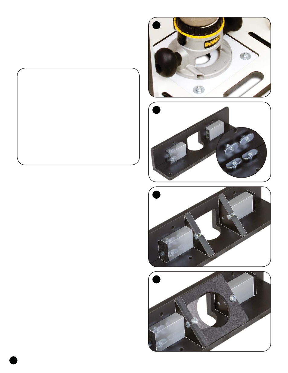
ROUTER FENCE ASSEMBLY
Insert eight 3/4" flathead screws (MF010) thru the
countersunk holes in Phenolic Fence Base (201C - 2 pcs.) and
start an oval nut (5760B - flat side first) on the ends of the
screws. Set the 2-1/2" wide horizontal Base on a flat surface
with the oval nuts facing up. Set the vertical Base on edge along
side it so their bit openings line up and the oval nuts are next
to each other. Slide a 2-1/4" Double Track (201G) onto four of
the oval nuts on one side of the bit opening, then repeat for the
opposite side. Roughly center each track on the oval nuts and
snug the screws for now. This assembly is guaranteed square
to within one degree. If you need it squarer, place paper shims
between the Double Tracks and the vertical Base.
See fig. 4.
Place a Dust Port Block (201D) on each end of the
Double Tracks next to the bit opening. Insert a 3" flathead
screw (MF032) thru the countersunk holes in both of the
Covers (201E), orient the Cover so the screw is closer to the
horizontal Base and insert the screw thru the opening in the
Double Track from the side opposite the Dust Port Blocks.
The threaded hole in the Dust Port Block must align with the
end of the screw. Orient the Dust Port Block to line up with
the screw, then start and tighten both screws. See fig. 5.
Insert a 1/2" barrel nut (5793B) into each on the holes in
the Dust Port Blocks and turn the nut so the cross hole aligns
with the slot in the edge of the Block. Insert a 5/8" screw
(5775B) thru one of the holes in the Dust Port Plate, align
the edge of the Plate with the Block and tighten the screw
in the barrel nut. Loosen the eight 3/4" screws holding both
Double Tracks (keep the Phenolic Fence Bases aligned)
and shift both as needed until the second Dust Port Block
aligns with the second hole in the Dust Port Plate. Attach
it with a 5/8" screw (5775B), center the entire assembly on
the Bases and tighten the eight 3/4" screws. See fig. 6.
3
4
5
6
201 Router Fence Parts List:
Part Description
Quantity
201A
24” Aluminum Fence. . . . . . . . . . . . . . . . . . . . . . . . . . . 1
201C
Phenolic Fence Base, 2 pcs. . . . . . . . . . . . . . . . . . . . . . 1
201D
Dust Port block. . . . . . . . . . . . . . . . . . . . . . . . . . . . . . . . 2
201E
Cover. . . . . . . . . . . . . . . . . . . . . . . . . . . . . . . . . . . . . . . . . 2
201F
Dust Port Plate . . . . . . . . . . . . . . . . . . . . . . . . . . . . . . . . 1
201G
2-1/4” Double Track . . . . . . . . . . . . . . . . . . . . . . . . . . . . 2
5760B
oval nuts. . . . . . . . . . . . . . . . . . . . . . . . . . . . . . . . . . . . . 14
MF010
1/4-20 x 3/4” flathead screw . . . . . . . . . . . . . . . . . . . . 8
MF032
1/4-20 x 3” flathead screw . . . . . . . . . . . . . . . . . . . . . . 2
5775B
1/4-20 x 5/8” screw . . . . . . . . . . . . . . . . . . . . . . . . . . . . 4
5793B
1/4-20 x 1/2” barrel nut . . . . . . . . . . . . . . . . . . . . . . . . 2
5548S
T-Knob w/1-1/2” stud. . . . . . . . . . . . . . . . . . . . . . . . . . . 2
BUSH050 3/4” OD x 3/8” long spacer. . . . . . . . . . . . . . . . . . . . . . 2
224
Guard . . . . . . . . . . . . . . . . . . . . . . . . . . . . . . . . . . . . . . . . 1
5503
1/2” thumb screw . . . . . . . . . . . . . . . . . . . . . . . . . . . . . . 2