Vortech 1986-1993 Ford 5.0 Mustang User Manual
Page 25
P/N: 4FA020-010
© 2009 Vortech Engineering, Inc.
All Rights Reserved, Intl. Copr. Secured
16APR09 v4.1(86-93 5.0 Mus (4FA v4.1))
13
14. IGNITION/BOOST CONTROL INSTALLATION
(High Output and Cobra systems only)
A. The Ignition/Boost Control unit has been prewired for
installation convenience. Installation is a simple matter of
disconnecting the stock connector at the ignition coil and
plugging in the new adapter. Then plug the stock connector
into the adapter.
B. The next step is to provide a good ground for the black wire
and mounting the box in as cool a place as possible under
the hood. The box should be mounted with the aluminum
cover on the bottom.
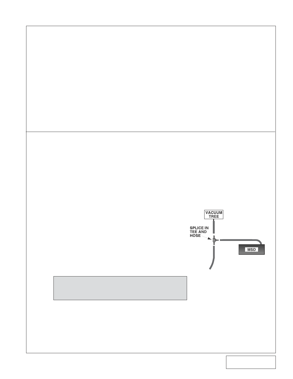
C. Using the supplied 5/32" hose and 5/32" tee, connect the vent
on the control unit to the FMU vacuum/pressure hose
(see graphic at right).
D. Route the Ignition/Boost Control wires through the firewall
from the interior side. Mount the knob in an easily accessible
place.
E. Connect the wires to the plastic oval wiring connector on
the Ignition/Boost Control unit using the snap-on connector
supplied in the Ignition/Boost Control kit.
NOTE: The wiring to the boost/control knob can be
matched to either of the corresponding wires in
the boost retard connector.
10. In the engine compartment, connect the flex hose from
the elbow extending through the hole to the elbow on
the supercharger.
11. Cut the MAF wires 3" to 4" away from the MAF
connector.
12. Slip 1" long sections of the supplied shrink tubing over
each wire before soldering.
13. Using the supplied wiring, solder wire extensions for the
MAF and connector through the fender well. Position
shrink tube over the solder joint and gently heat until
the tube seals the joint.
14. Replace the inner fender lining.
13. AIR FILTER ASSEMBLY, cont'd.
Fig. 14-a