Vortech 1986-1993 Ford 5.0 Mustang User Manual
Page 22
P/N: 4FA020-010
© 2009 Vortech Engineering, LLC
All Rights Reserved, Intl. Copr. Secured
16APR09 v4.1(86-93 5.0 Mus (4FA v4.1))
10
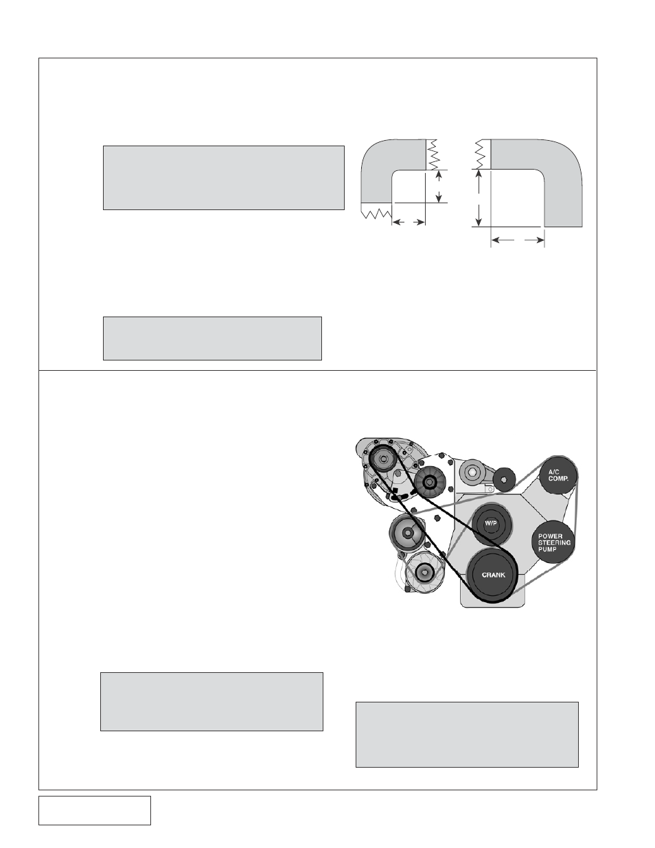
9. RADIATOR HOSE
A. From the stock radiator hose, make two 90° elbows by trimming as
shown. The first is with 3" long legs for the thermostat housing end.
The second, with 2" long legs, is from the middle of the stock hose and
attaches to the radiator.
B. Place the stainless water pipe between the
two hoses placing the shorter leg nearer the
radiator.
C. Position the hoses and tube so there is ample
overlap for sealing and secure with provided clamps.
D. Refill radiator and coolant bottle.
A. Secure the factory spring tensioner assembly
to the Vortech belt tensioner mounting bracket
using the 1/2" carriage bolt.
B. Replace the locking type nut on the A/C
mounting bracket stud closest to the water
pump with a standard nut.
C. Depending on Ford's manufacturing
tolerances,
it may be necessary to trim
about 1/8" off the edge of the flange on the
A/C mounting bracket to provide room for
the tensioner mounting bracket.
D. Install the tensioner mounting bracket
with tensioner between the supercharger
mounting plate and A/C bracket stud using
two standard flat washers as a spacer. Secure
with two 3/8-16 x 1" bolts and washers and
a 3/8-16 nut.
E. Reinstall radiator shroud and fan assembly.
(Slight shroud trimming may be required on
S.H.O. applications.)
F. Reinstall stock accessory belt. (On S.H.O.
applications, use the supplied 888 belt for
the accessory drive.)
10. ACCESSORY BELT TENSIONER MOUNTING BRACKET
NOTE: Make sure the cooling system
is completely full. Air is often
trapped in 5.0 systems.
NOTE: Check the accessory belt ten-
sioner pulley alignment. It may
be necessary to add or remove
a washer to the stud behind the
tensioner bracket.
NOTE: S.H.O. V-7 APPLICATIONS - The
10-rib supercharger pulley supplied in
this kit fits close to the upper radiator
hose. More trimming than shown in
Fig. 9-a may be required.
NOTE: On S.H.O. applications, a fan
spacer, studs and nuts have been
supplied. Install these items be-
fore installing the fan
Fig. 10-a
2"
2"
3"
3"
Fig. 9-a