Vortech 1986-1993 Ford 5.0 Mustang User Manual
Page 14
P/N: 4FA020-010
© 2009 Vortech Engineering, LLC
All Rights Reserved, Intl. Copr. Secured
16APR09 v4.1(86-93 5.0 Mus (4FA v4.1))
2
3. OIL DRAIN (Engine oil fed kits only. V3 kits, skip
ahead to section 5)
A. To provide an oil drain for the supercharger, it is necessary
to make a hole in the oil pan. Locate and mark hole per
diagram. It is best to punch the hole rather than drill.
B. Remove paint around the hole area.
C. Use a small center punch to perforate the pan and expand
hole. Switch to a larger diameter punch and expand the hole
further to approximately 9/16" diameter. Most punches are
made from hexagon material and may be placed in a socket
with an extension to make this procedure easier.
D. Tap the hole with a 3/8" NPT tap approximately1/4" deep.
Pack the flutes of the tap with heavy grease to hold chips.
Use a small magnet to check for any stray chips.
E. Thoroughly clean the threaded area. Apply a small amount
of silicone sealer to the new threads. Apply more sealer to
the 3/8" NPT hose fitting and secure in hole. Make sure a
seal is formed all around the fitting.
F. Drain the engine oil and change the filter.
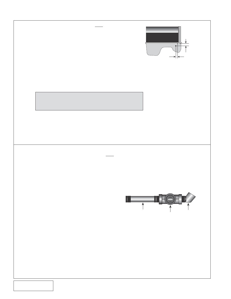
4. OIL FEED LINE (Engine oil fed kits only. V3
kits, skip ahead to section 5)
A. Remove the oil pressure sender and mounting
boss fitting from the engine. These are found on
the engine's left side just ahead of the oil filter.
B. Thread the supplied 3" x 1/4" NPT nipple into the
block using engine oil on the threads. Pipe tape,
paste or other sealant is not recommended as it
might loosen and cause blockage of the oil feed
orofice, resulting in supercharger failure.
C. Thread the supplied 1/4" female TEE into the
nipple. Rotate the TEE so that the center leg
points toward the front of the vehicle. Thread
the 45° elbow into the leg of the TEE pointing
toward the side of the vehicle.
D. Install the factory sending unit into the 45°
elbow.
E. Thread the supplied flare fitting into the remaining
leg of the TEE.
F. Connect the red oil feed line to the fitting at the
pressure sender and route it behind the A/C
mounting plate to the supercharger location.
Cover the end of the hose with a clean plastic
bag. Connect the line to the supercharger with
the flare fitting provided.
Fig. 3-a
Fig. 4-a
NOTE: This method of rolling over the lip of the hole and
tapping it works very well if carefully done and
should cause no problems.
ENGINE BLOCK
1/2” REAR FROM FIRST BOLT ON SIDE
FRONT
1-3/4”
BELOW
PAN LIP
3” NIPPLE
1/4” TEE 45°ELBOW