Ee “using the, Using the airfiber configuration interface – Ubiquiti Networks airFibe5 User Manual
Page 17
14
Chapter 2: Installation
airFiber
®
AF5/AF5U User Guide
Ubiquiti Networks, Inc.
Using the airFiber Configuration Interface
Before You Begin
Note:
The instructions in this section assume that
you are viewing the Antenna Alignment screen of
the Master; however, you can also use the Antenna
Alignment screen of the Slave.
To access the airFiber Configuration Interface:
1. Make sure that your computer is connected to the
Management port on the airFiber AF-5.
2. Configure the Ethernet adapter on your computer with
a static IP address on the 192.168.1.x subnet.
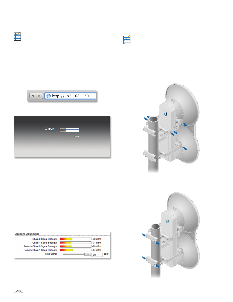
3. Launch your web browser. Type http://192.168.1.20 in
the address field and press enter (PC) or return (Mac).
4. The login screen will appear. Enter ubnt in the
Username and Password fields. Click Login.
5. The Main tab of the airFiber Configuration Interface
appears. Click the Tools drop-down list at the top right
corner of the page.
6. Click Align Antenna. You will use the Align Antenna
tool to point and optimize the antenna in the direction
of maximum link signal. (The Antenna Alignment
window is designed to refresh every 250 milliseconds.
See “Align Antenna” on page 38 for more details.)
7. The Antenna Alignment window appears, displaying
the Signal Strengths for both airFiber radios. The Chain
Signal Strength bar graphs display the Signal Strengths
for the local airFiber AF-5 you have accessed, while the
Remote Signal Strength bar graphs display the Signal
Strengths for the remote airFiber AF-5.
Establishing a Link
Adjust the positions of the Master and the Slave to
establish a link.
Note:
The Master must be aimed first at the Slave
because the Slave does not transmit any RF signal
until it detects transmissions from the Master.
1. Ensure that the following bolts and nuts are loose:
• Four Pre-Installed M10x25 Flanged Bolts on the
airFiber radio (two on each side)
• Four M10 Hex Nuts used to lock the elevation
alignment on the Upper Mount Bracket (two on
each side)
2. Ensure that the pole mount is snug yet the four M10
Hex Nuts attaching the Pole Clamps are loose enough to
allow rotation around the pole for azimuth alignment.