Alignment, Tips, Determining the received signal level – Ubiquiti Networks airFibe5 User Manual
Page 15: Using the led displays, Establishing a link
12
Chapter 2: Installation
airFiber
®
AF5/AF5U User Guide
Ubiquiti Networks, Inc.
Alignment
Tips
• To accurately align the airFiber radios for best
performance, you MUST align only one end of the link at
a time.
• For more convenient alignment, you may consider using
long-range scopes (not included) temporarily attached
to your airFiber radios.
• You may need to use additional hardware to
compensate for issues such as the improper orientation
of a mounting pole or significant elevation differences
between airFiber radios.
Determining the Received Signal Level
There are three methods for determining the received
signal level:
• LED Displays (See the next column.)
• airFiber Configuration Interface (See “Using the
airFiber Configuration Interface” on page 14.)
• Audio tone (Optional equipment required. See “Using
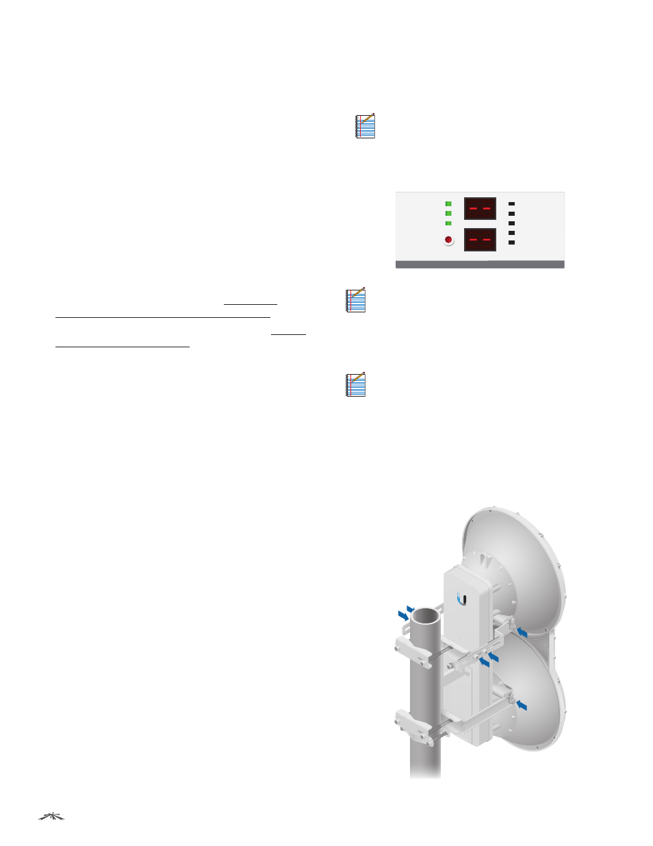
Using the LED Displays
Before a link is established, the Master’s LED Display looks
like this:
• GPS and Master LEDs are solidly lit
Note:
The GPS LED may not be lit if there is a
weak GPS signal. A GPS signal is not required for
alignment.
• Link Status LED flashes (Normal Flash 1:1)
• Remote and Local LED Displays show a double dash
GPS
MASTER
LINK
RESET
OVERLOAD
8X
6X
4X to 0.25X
REMOTE
LOCAL
AUX
MANAGEMENT
DATA
ACT
SPEED
ACT
SPEED
Note:
The Local LED Display may briefly flash a
large number (such as 95) when there is no link.
Establishing a Link
Adjust the positions of the Master and the Slave to
establish a link.
Note:
The Master must be aimed first at the Slave
because the Slave does not transmit any RF signal
until it detects transmissions from the Master.
1. Ensure that the following bolts and nuts are loose:
• Four Pre-Installed M10x25 Flanged Bolts on the
airFiber radio (two on each side)
• Four M10 Hex Nuts used to lock the elevation
alignment on the Upper Mount Bracket (two on
each side)