13 chapter 2: installation airfiber – Ubiquiti Networks airFibe5 User Manual
Page 16
13
Chapter 2: Installation
airFiber
®
AF5/AF5U User Guide
Ubiquiti Networks, Inc.
2. Ensure that the pole mount is snug yet the four M10
Hex Nuts attaching the Pole Clamps are loose enough to
allow rotation around the pole for azimuth alignment.
3.
Master
Visually aim the Master at the Slave. To adjust
the Master’s position:
a. Rotate the airFiber radio on the pole to align the
azimuth.
b. Use the hex nut on the Elevation Rod to adjust the
elevation.
Note:
Do NOT make simultaneous adjustments on
the Master and Slave.
4.
Slave
Visually aim the Slave at the Master. To adjust the
Slave’s position:
a. Rotate the airFiber radio on the pole to align the
azimuth.
b. Use the hex nut on the Elevation Rod to adjust the
elevation.
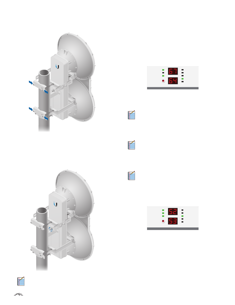
5. Check to see if a link is established. Ensure that the Link
Status LED is solidly lit green and the Remote and Local
LED Displays of the Slave are displaying signal levels.
GPS
MASTER
LINK
RESET
OVERLOAD
6X
8X
4X to 0.25X
REMOTE
LOCAL
AUX
MANAGEMENT
DATA
ACT
SPEED
ACT
SPEED
6.
Slave
Aim the Slave at the Master to achieve the
strongest signal level on the Remote LED Display of the
Slave.
Note:
Values on the LED Displays are displayed in
negative (-) dBm. For example, 67 represents a
received signal level of -67 dBm. Smaller numerical
values indicate stronger received signal levels. For
example, a reading of 49 is stronger than a reading
of 55.
Note:
Maximum signal strength can best be
achieved by iteratively sweeping through both
azimuth and elevation.
7.
Master
Aim the Master at the Slave to achieve the
strongest signal level on the Remote LED Display of the
Master.
Note:
If the Overload LED lights up, identify
and eliminate any source of strong in-band
interference.
8. Repeat steps 6 and 7 until you achieve a symmetric
link, with the signal levels within 1 dB of each other.
This ensures the best possible data rate between the
airFiber radios.
GPS
MASTER
LINK
RESET
4X to 0.25X
OVERLOAD
8X
6X
REMOTE
LOCAL
AUX
MANAGEMENT
DATA
ACT
SPEED
ACT
SPEED
9. Lock the alignment on both airFiber radios by
tightening the nuts and bolts.
10. Observe the Local and Remote LED Displays of each
airFiber radio to ensure that the values remains
constant while tightening the nuts and bolts. If any LED
value changes during the locking process, loosen the
nuts and bolts, finalize the alignment of each airFiber
radio again, and retighten the nuts and bolts.
11. For each airFiber radio, close the port cover and ensure
that the Ethernet cable stays in the cable feed slot.