Iv. control panel – SurgeX SX-AX20 User Manual
Page 12
SX-AX15 (20) Setup and Control Utility User Manual
Page 11
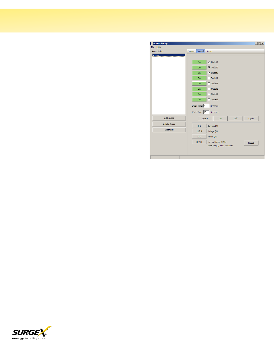
IV. Control Panel
The Control Panel is located just below the
Operations Tabs when the SCU is in Control mode.
The control mode is entered by clicking Login on
the Connect Panel, selecting an Axess from the
select list box that has a saved user name and
password, or by clicking on the control button in the
task bar. The control panel will not be displayed if
no user name and password combination has been
entered on the connect panel. The control panel is
displayed as a blank panel if it is accessed with an
invalid user name and password. The control panel
contains the following elements:
Outlet Check Boxes
The outlet check boxes are used to select
the outlets to be controlled. The text next to
each check box is the actual outlet name
retrieved from the Axess. All check marks
are cleared whenever an Axess is selected
from the list box.
Outlet Status Bars
The outlet status bars are used to display the status of the outlets. The background color
indicates the current state of the outlet: green for on, and grey for off. The text in the
panel tells the user weather the outlet is on, off, rebooting or cycling.
Delay Time
Delay Time is the amount of time that will be delayed between outlet changes when
making changes to multiple outlets. The Delay Time edit box displays the delay time
currently in use and allows for the specification of a new delay time. Acceptable values
are 0-99 seconds. The new delay time is applied when the On, Off, or Cycle command is
sent to the Axess.
Cycle Time
The cycle time edit box displays the cycle time currently in use and allows for the
specification of a new cycle time. The new cycle time is applied when the On, Off, or
Cycle command is sent to the Axess. Acceptable values are 1-99 seconds.
Current Display Bar
The Current display bar displays the total current measured through all outlets. The
background color will be grey when the current is in the normal range, yellow when a low
current alarm is active, and red when a high current alarm is active.