StorCase Technology DE200i-SWC User Manual
Page 17
StorCase Technology, Inc.
DE200i-SW/SWC User's Guide - Rev. C01
10
Installation
TYPICAL 2MM DRIVE ID PIN CONFIGURATION
(Applies to DE200i-SW only)
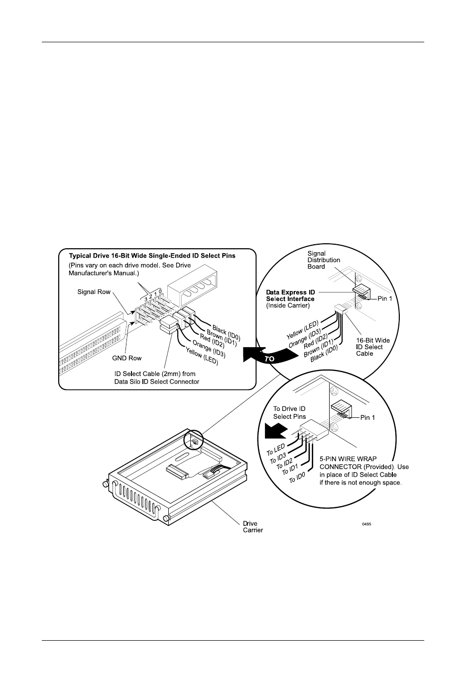
Figure 7 illustrates a typical SCSI ID select connection to a drive with 2mm ID select pins. In
most cases, the drive manufacturer labels each pair of SCSI ID select pins in their significant
bit order (0, 1, 2, 3 as shown in Figure 7). In other cases, the manufacturer does not label
these pins in their significant bit order, but instead, assigns pin numbers only. In any case,
all odd numbered pins or all even numbered pins will be the signal row. The wires on the wire
harness connect to the positive pin (or signal pins) on the drive. Refer to the device
manufacturer's documentation for additional pin numbering and jumper option information.
Attach the ID select cable to the drive using the 2mm connectors. Align the ID0 pin with the
black wire. Attach the other end of the ID select cable to the ID select connector located on
the signal distribution board, inside the carrier. Refer to the manufacturers documentation
to disable termination on the drive.
Figure 7: Typical SCSI ID Select Connections (2mm Drive Pins)