Spectrum Controls 1746sc-INO4vi User Manual
Page 41
Chapter 5: Testing Your Module
31
Interpreting The LED
Indicators
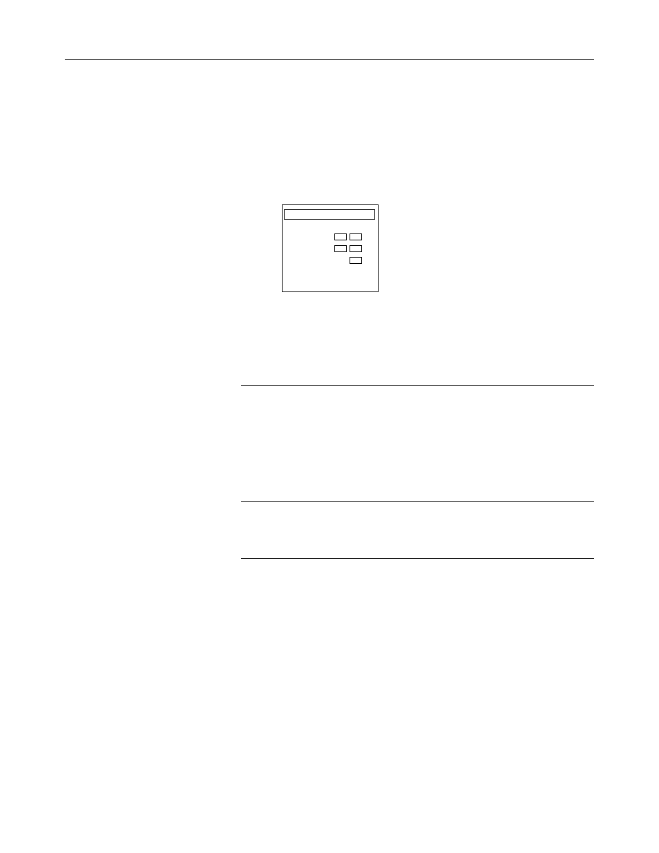
Your output module has 5 LEDs: 4 channel status LEDs (numbered 0–3
for channels 0–3, respectively) and 1 module status LED.
Figure 6. LED block
Module Status
Channel
Status
Isolated Analog
0
1
2
3
OUTPUT
Use the following table to interpret the LEDs:
Table 12. LED definition
If the module
And the channel
status LED is…
status LED is…
Then...
On
On
The channel is enabled.
Blinking
One of the following channel errors occurred:
• circuit open (4–20 mA outputs only)
• signal is near or beyond end of range
• channel configured incorrectly
Refer to the following section,
Troubleshooting.
Off
Either your module is powering up or the channel
is disabled.
Off
Off
Either the power is off, the module is powering up,
or a module fault occurred. Cycle power. If the
condition persists, call your local distributor or
Spectrum Controls for assistance.
Interpreting I/O Error
Codes
I/O error codes appear in word S:6 of the SLC processor status file. The
first two digits of the error code identify the slot (in hexadecimal) with
the error. The last two digits identify the I/O error code (in hexadecimal).
The error codes that apply to your module include (in hexadecimal):
• 50–5E
• 71 (watchdog error)
• 90–94
For a description of the error codes, refer to the Allen-Bradley Advanced
Programming Software (APS) Reference Manual, Allen-Bradley
publication 1746-6.11.