Spectrum Controls 1746sc-INO4vi User Manual
Page 32
22
SLC 500
™
Isolated Analog Output Modules
and the low limit (output word 6) must be lower than the high limit
(output word 7).
Example – Suppose you have four valves with a
±
10 V operating range,
and you want to use the Engineering Units data format. For this
application, you would use the following bit settings for the channel
configuration bytes (output words 4 and 5):
0
0
0
0
15
0
O:e.4
Address
O:e.5
0
0
0
1
0
0
0
0
0
0
0
1
0
0
0
0
0
0
0
1
0
0
0
0
0
0
0
1
Suppose, also, that you would like to set the output limits to -2 V and
+8 V. After entering the above bit settings for output words 4 and 5, you
would enter the following for output words 6 and 7:
1
1
1
1
15
0
O:e.6
Address
O:e.7
1
0
0
0
0
0
1
1
0
0
0
0
0
0
0
1
1
1
1
1
0
1
0
0
0
0
0
0
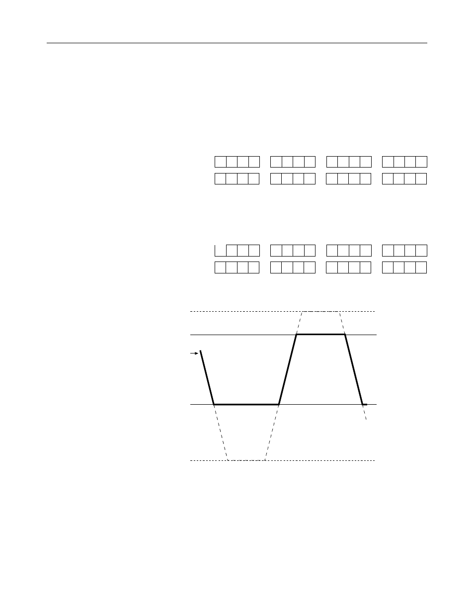
Your module will now limit the output signal as shown below.
Data Limit High
Data Limit Low
Output Signal
+10.25 V
+8 V
-2 V
-10.25 V
Note that whenever the requested output data values meet or attempt to
exceed the output data limits, your module sets bits 10 or 11 in the
channel status word to indicate a limit error. Note also that words 0
through 3 of the input image file (addresses I:e.0 through I:e.3) reflect the
requested output data values and are not truncated.