SOR Single Point Ultrasonic Level Switch User Manual
Page 9
Form 771 (08.13) ©SOR Inc.
9/20
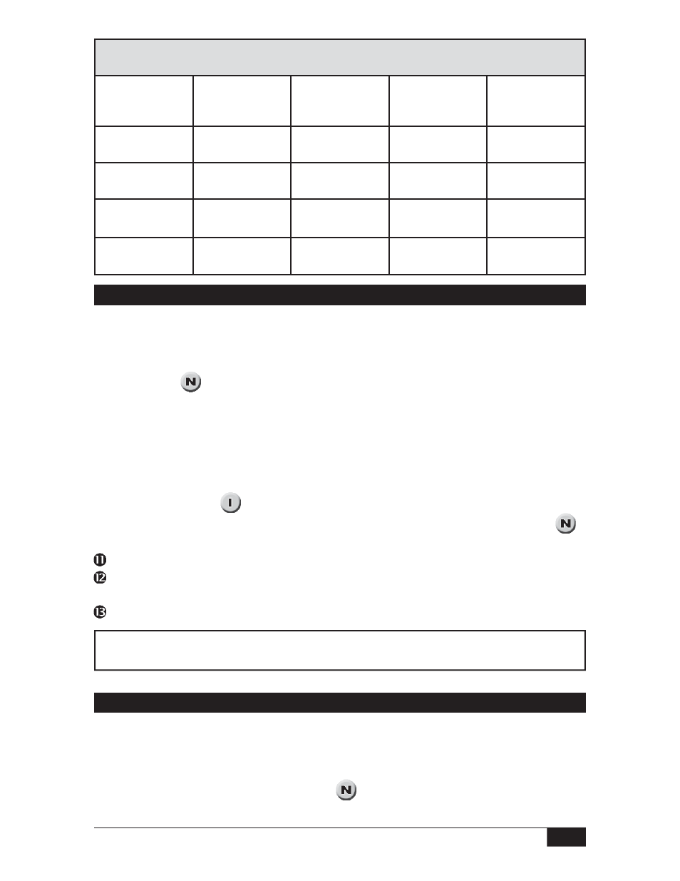
Current Output Chart
Yellow LED
(Dry)
Red LED
(Wet)
Current Meter
(+ 1mA)
Sensor
Status
Failure Mode
8 mA
Dry
__
16 mA
Wet
__
5 mA
__
5 mA
19 mA
__
19 mA
LED on
LED off
Sensor Replacement
Disconnect power to the unit.
Remove the housing cover.
Remove two mounting screws and slide out PC board to expose the sensor connections
J1 and J2. (See
)
Disconnect the sensor wires from J1 and J2.
Unscrew the sensor from the housing.
Apply thread sealant to the male threads of the new sensor.
Thread the new sensor into the bottom of the housing.
Discharge the sensor. Connect the center conductor and shell of sensor wire end as
shown on page 4. (See
)
Connect the sensor wire (T) into the J2 mini-phono jack on the circuit board. (See
)
Connect the sensor wire (A) into the J1 miniphono jack on the circuit board.
Slide the PC board into the grooves in the plastic ring inside the housing.
Replace the two mounting screws into the plastic ring: these screws are self-tapping.
Do not overtighten.
Reconnect power and replace the housing cover.
Replacement Sensors
See Form #973, Ultrasonic Catalog for replacement sensor model numbers.
Circuit Board Replacement
Disconnect power to the unit.
Remove the housing cover.
Remove two mounting screws and slide out PC board.
Disconnect sensor plugs J1 and J2. (See
)
Slide the new board into the control housing.