Viscous sensor installation (series 371-v) – SOR Single Point Ultrasonic Level Switch User Manual
Page 3
Form 771 (08.13) ©SOR Inc.
3/20
Open Sump or Basin
Do not suspend the unit by rigid conduit installed
in the electrical hub. When installing the unit over
an open sump or basin, use a suitable bracket to
support the instrument.
Open Sump
Locally
Supplied
Bracket
CE Marking Sensor Installation (notch type sensors only, Series 371-N)
Shield Beads
Three beads are included with your CE marked unit.
Two of the beads are 5/8” dia x 1/2” long. The other
bead is 3/8” dia x 3/4” long (save this bead for the
electrical connection beginning on page 5).
Disconnect the sensor leads from the circuit board.
Slide one 5/8” dia. bead onto each lead.
Reinstall the sensor leads into the circuit board.
Push the beads to the bottom of the housing. (See
)
Sensor
Wires
Sensor
Electronics
Housing
Shield
Beads
NOTE: The instrument must be positioned so that
overfl ow does not fl ood electrical housing. (See
)
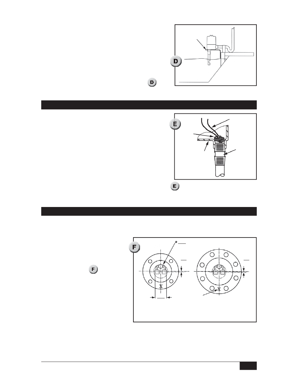
Viscous Sensor Installation (Series 371-V)
Vertical or horizontal (flange only) mounting is supported for the viscous sensor. A 3”
(76.2mm) minimum opening is required for insertion.
76.2
3.00
minimum opening required (typ.)
5.9
0.23
Bottom View Viscous
Sensor with 8-Hole Flange
Alignment mark, (other side)
position at 6 o’clock (typ.)
Bottom View Viscous
Sensor with 4-Hole Flange
62.1
2.44
(typ.)
5.9
0.23
C
L
of fl ange
An alignment mark X stamped on
the dry face of the flange below
the housing shows sensor cav-
ity orientation. (See
) When
mounting the viscous
sensor horizontally, optimum
drainage occurs when the X mark
is located in the 6 o’clock position.
Take care during installation to
prevent damage to the sensor
end. Slight bending of the sensor may result in loss of sensitivity due to misalignment of
the ultrasonic crystals.