SOR Single Point Ultrasonic Level Switch User Manual
Page 6
6/12
Form 712 (05.13) ©SOR Inc.
B. Line Power Terminals
Terminals are provided for incoming power leads on the nine-position PC board terminal strip.
Supply voltage for each PC board is printed on the green insulator card. Make sure that the
available line voltage matches device’s power supply.
C. Ground Terminals
The housing and the PC Board must be connected to ground. Ground (earth) screws are
provided on the nine-position PC board terminal strip and on the housing floor.
If extra clearance is required for connection to the ground screw on the housing floor, the
PC board can be removed and reinstalled according to Field Replacement–PC Board on
page 11.
C
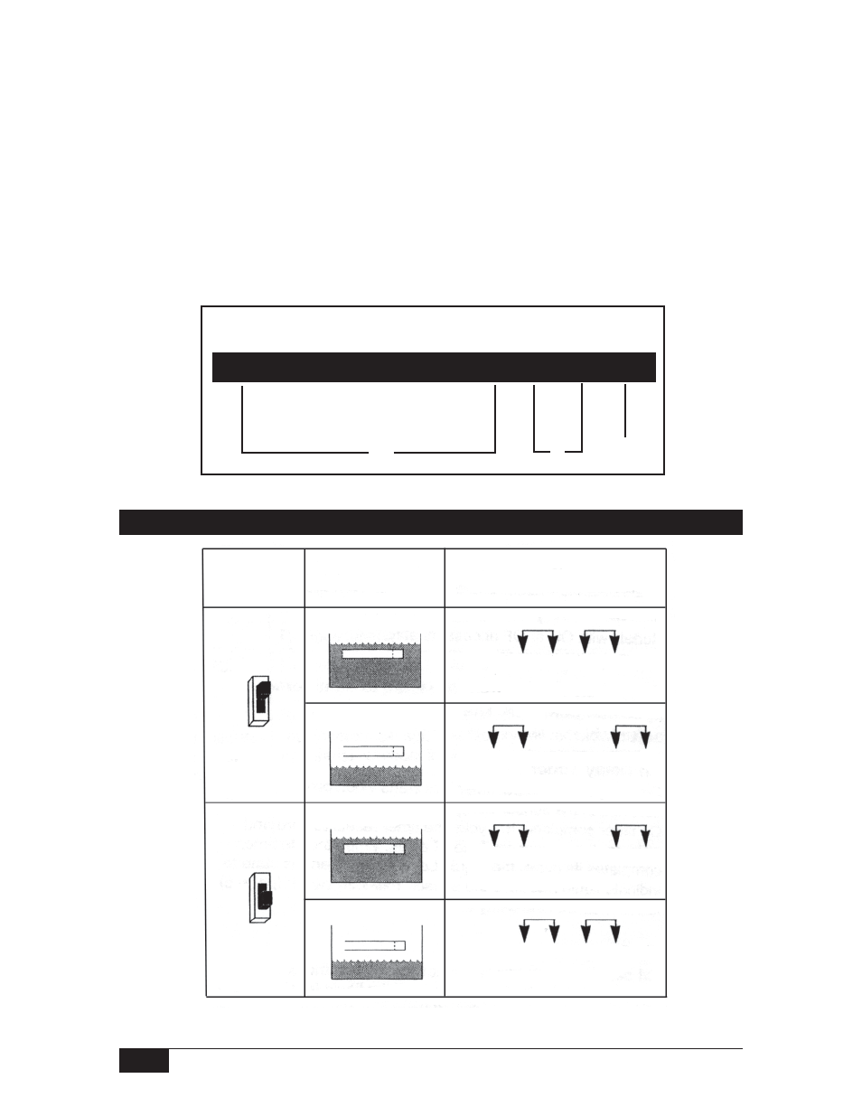
Nine-Position Terminal Strip
NC1 C1 NO1 NO2 C2 NC2 L1 N GND
B
A
Failsafe Switch (Models with OF, OD, or FS accessories only)
Failsafe
Mode
Switch Position
Sensor
Condition
Liquid Level
Relay Contact A
Continuity Chart
Relay
energized on
high level
Liquid above sensor
Liquid below sensor
Liquid above sensor
Liquid below sensor
NC1 C1 NO1 NO2 C2 NC2
Relay Energized
NC1 C1 NO1 NO2 C2 NC2
Relay De-energized
NC1 C1 NO1 NO2 C2 NC2
Relay De-energized
NC1 C1 NO1 NO2 C2 NC2
Relay Energized
Relay
energized on
low level
HI/LO
HI/LO