SOR Single Point Ultrasonic Level Switch User Manual
Page 5
Form 712 (05.13) ©SOR Inc.
5/12
Electrical Connection (Applies to all models)
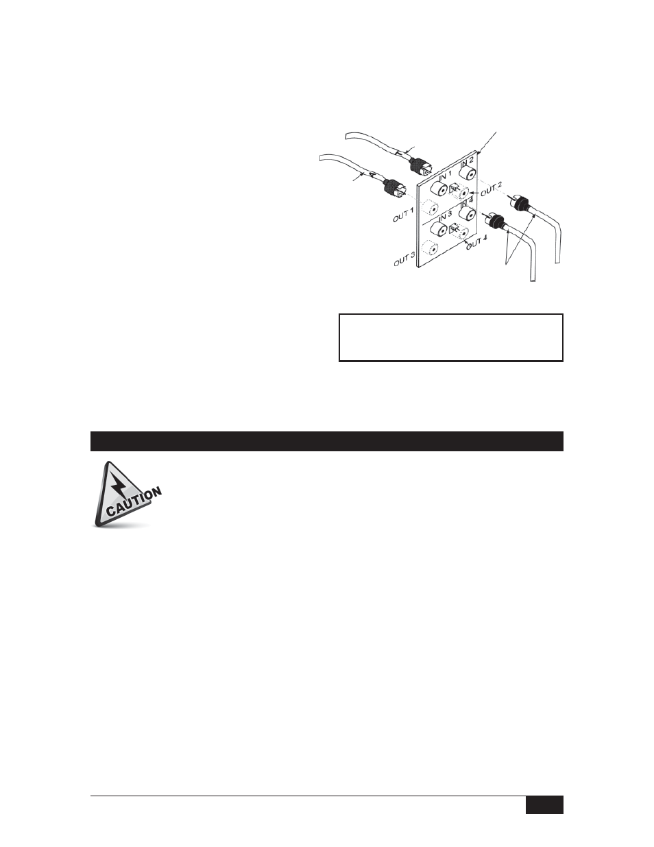
Sensor Connections Inside Sensor Base
Inside the sensor base, a remote interconnect board rests in a plastic holder.
Slide the interconnect board up. Attach the sensor coax connectors to the
interconnect board as follows:
Remote
Interconnect
Board located
inside sensor
base
OUT connections are located on the opposite
side of the board from the IN connections.
Do not use positions 3 and 4 to connect wires.
Connect one sensor cable to IN 1.
Connect the other sensor cable to IN 2.
Attach the extension cables to the
interconnect board as follows:
Connect cable A to OUT 1.
Connect cable T to OUT 2.
Plug in Connections Inside
Electronics Housing. Plug sensor
extension cables onto the PC
board as follows:
Connect cable A and cable T to the
Sensor Lead Connections. See PC Board
Arrangement on page 2 to locate Sensor
Lead
Connections.
Tip-sensitive sensor connections are not sensitive to position. Sensor Lead Connection
wires may be interchanged without affecting the performance of the instrument.
A nine-position terminal strip provides connections for DPDT Liquid Level Relay Contacts,
Line Power and Ground. Terminal positions are labeled on the green insulator card as
shown on Page 6.
A. Liquid Level Relay Contact Terminals
On units without OD, OF, or FS accessories, there is no fail-safe switch. The normal
operation of the unit is fail-safe hi. When the sensor is dry, the relay is de-energized; the
normally closed position (NC) and common (C) are in contact. When the sensor is wet, the
relay is energized; the normally open position (NO) and common (C) are in contact.
On units with OD, OF, or FS accessories, there is a failsafe switch. The failsafe switch is
located on the upper right hand corner of the circuit board with contact terminals facing
away from you (see circuit board illustration on the front cover). Refer to Page 6 for
switch options.
Electrical power must be disconnected from explosion proof models before
the cover is removed. Failure to do so could result in severe personal injury
or substantial property damage.