Wiring for dpdt relay dpdt relay schematic – SOR 1550 Top Mounted Level Switch User Manual
Page 2
2/8
Form 865 (11.13) ©SOR Inc.
NC 2
NO 2
NC 1
NO 1
5
6
4
3
7
2
1
8
Switch Capsule
Black Lead
White Lead
C2
C1
Power
Supply
Relay Coil
SPST Reed
Switch Capsule
SPDT Reed
Switch Capsule
Common Black Lead
Common Black Lead
Normally Open Blue Lead
Normally Closed White Lead
Normally Open White Lead
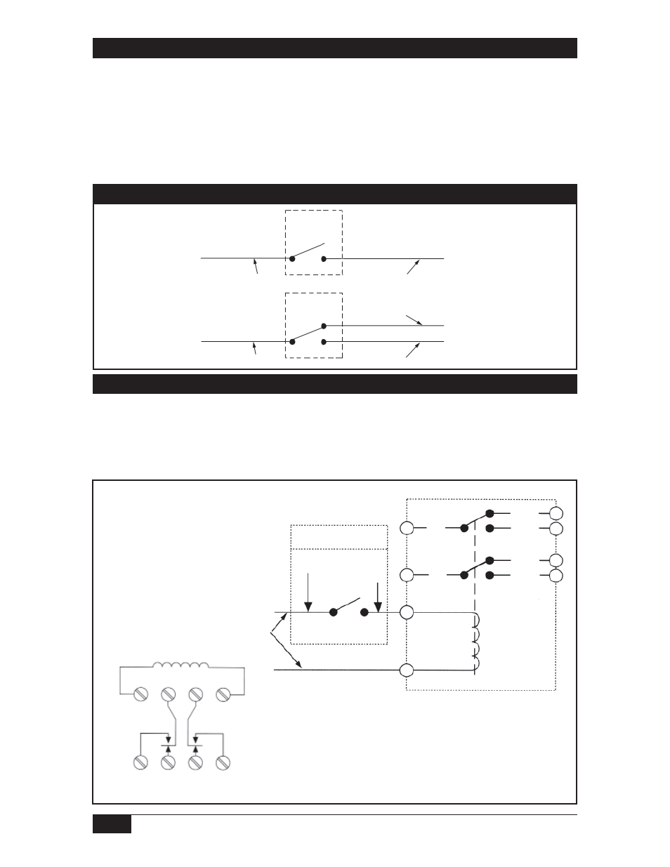
For Type 1550 Level Switches equipped with DPDT relays, a wiring schematic and pin
position schematic is shown below. When the 1550 is actuated, the coil will energize and
“make” both NO1 and NO2 while it will “break” NC1 and NC2. This provides a DPDT circuit.
Wiring for DPDT Relay
DPDT Relay Schematic
3
NO1
2
1
8
7
C2
C1
4
NC1
5
NC2
6
NO2
Wiring for SPST and SPDT Switch Operation
Safety Integrity Level (SIL) Installation Requirements
The SOR pressure switches have been evaluated as Type-A safety related hardware.
To meet the necessary installation requirements for the SIL system, the following
information must be utilized:
Proof Test Interval shall be one year.
Units may only be installed for use in Low Demand Mode.
Products have a HFT (Hardware Fault Tolerance) of 0, and were evaluated in a
1oo1 (one out of one) configuration.
Form 1538 (03.12) ©2012 SOR Inc.