Multiple switch chamber installation – SOR Sealed Level Switches User Manual
Page 4
4/8
Form 1428 (01.14) ©SOR Inc.
ISO-900
1
152.4
304.8
TO
6.0
12.0
RECOMMENDED
TO LOWEST
SET POINT
203.2
406.4
TO
8.0
16.0
RECOMMENDED
304.8
457.2
TO
12.0
18.0
RECOMMENDED
LIQUID
SET POINTS
152.4
304.8
TO
6.0
12.0
PRODUCT C
ALL DIME
UNLESS O
PROCESS TANK
THREE 2210
LEVEL SWITCHES
WITH EXTERNAL
CHAMBERS
50.8
2.0 HEADER PIPE
ISOLATION VALVE
25.4
1.0 PIPE TO
EACH CHAMBER
ELBOW
TEE TO
PROCESS TANK
SUPPLY
HEADER
VENT
HEADER
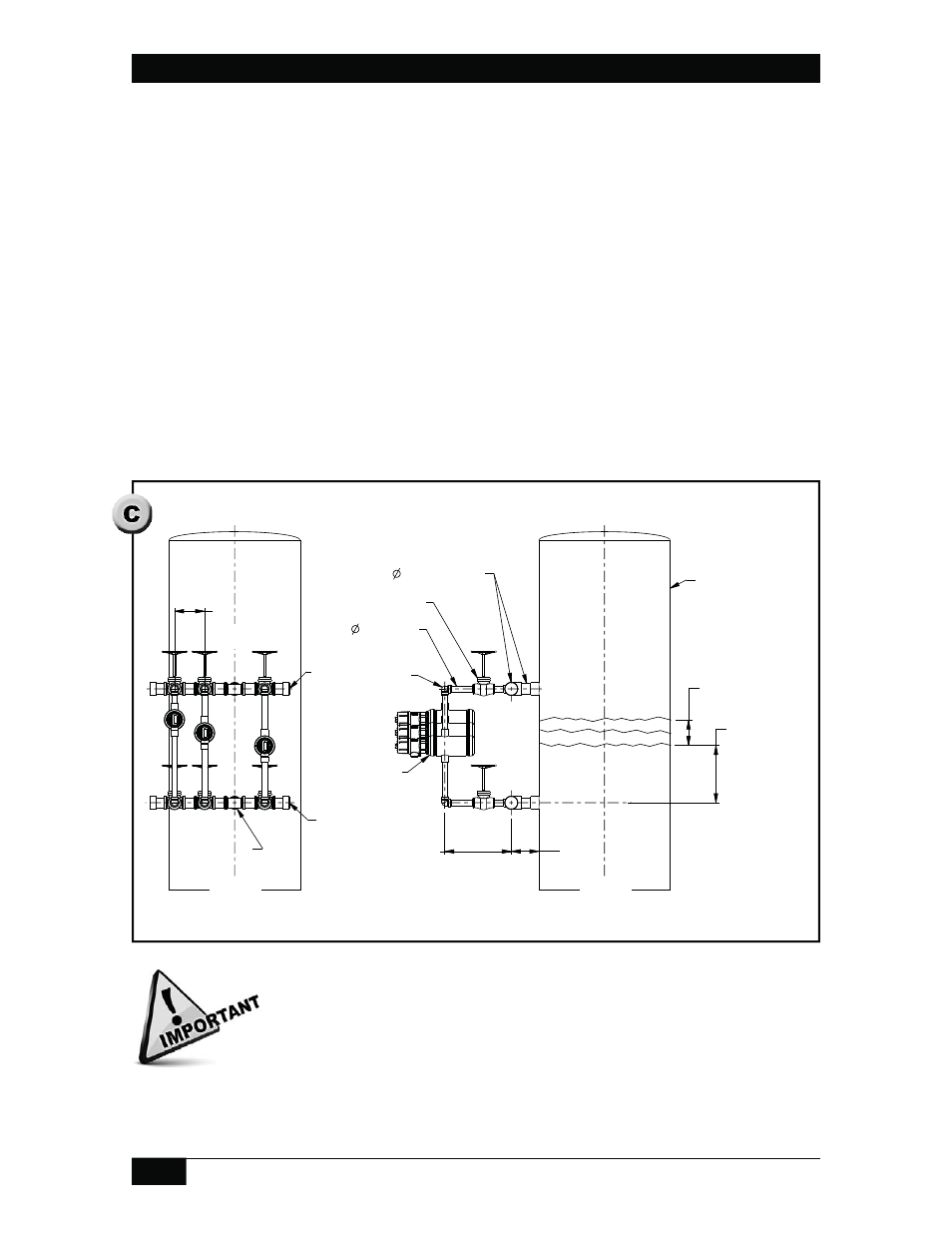
Multiple Switch Chamber Installation
Deviating from any of these recommendations may adversely affect
operation of the level switch by restricting liquid fl ow into the switch
chamber. The recommended dimensions leave adequate space for
isolation valves, fi ttings and insulation. Structural support (not shown)
must be provided for level switch chambers.
The header pipe diameter for three (3) or four (4) chambers needs to be two times the
process connection diameter. For 1” (25mm) process connections, the pipe header must
be 2” (50mm) in diameter. This includes pipe connecting the header to the process,
fittings, valves and other pipe equipment installed as part of the header piping. Headers
should be arranged to use one elbow or tee to connect to the process pipe or tank.
Pipe connecting the header to individual chambers can be the same size as the process
connection on the switch chamber. Fittings and valve diameters must also be equal
to or greater than the process connection diameter. One elbow is recommended to
connect the level switch chamber to the header pipe.
Install each chamber so that the actuate or deactuate point is at the desired process
liquid level. See Single Switch Chamber Note 2 for set point locations.
Locate the header 8” to 16” (200mm to 400mm) away from the process tank.
Locate switch chamber process connection 12” to 18” (300mm to 450mm) away from
the header pipe.
Horizontal spacing of level switch chambers should be 6” to 12” (150mm to 300mm).
Drawing 0390736