Single switch chamber installation – SOR Sealed Level Switches User Manual
Page 3
Form 1428 (01.14) ©SOR Inc.
3/8
Insulation of the control chamber is acceptable, but switch housing and
cover must not be insulated.
Not following these installation instructions, including pipe and valve
diameter and pipe lengths can affect operation of the switch, including
differential. See Single Switch Chamber Installation
and Multiple
Switch Chamber Installation
.
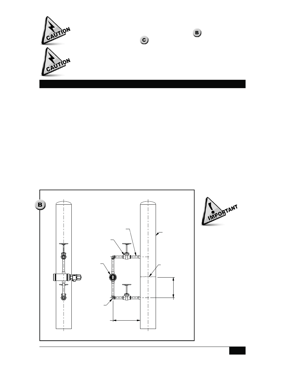
Locate switch chamber process connection 12” to 24” (300mm to 600mm) away from
the process pipe or tank.
Locate the switch chamber so that the switch actuates or deactuates at the desired level.
For liquids with a specific gravity of 1.0, switch actuation will occur approximately 3/4”
(20mm) above the chamber centerline and deactuation will occur at approximately 3/8”
(10mm) above the chamber centerline. Consult factory for other specific gravity values.
Connect the bottom chamber process connection to the process pipe or tank 6” to 12”
(150mm to 300mm) below the centerline of the chamber. This will ensure liquid level
in the switch chamber is as close as possible to process liquid level.
Inside diameter of piping, including elbows, tees and valves, must be equal to or
greater than process connection diameter.
One elbow is recommended to connect the level switch with the process pipe or tank.
Single Switch Chamber Installation
Deviating from any
of these instructions
may adversely affect
operation of the level
switch by restricting
liquid fl ow into the
switch chamber.
The recommended
dimensions allow
adequate space for
isolation valves,
pipe fi ttings and
insulation. Structural
support (not shown)
must be provided
for level switch
chambers.
152.4
304.8
TO
6.0
12.0
RECOMMENDED
304.8
609.6
TO
12.0
24.0
RECOMMENDED
ELBOW
ISOLATION
VALVE
2210 LEVEL
SWITCH WITH
EXTERNAL
CHAMBER
LIQUID SET
POINT
PROCESS TANK
PIPE
Drawing 0390736