Installation – SOR Sealed Level Switches User Manual
Page 2
2/8
Form 1428 (01.14) ©SOR Inc.
ISO-9001
14685 W 105TH ST LENEXA, K
913-888-2630
SORINC.COM
459.6±14.2
18.10±0.56
112.6
4.43
118.6
4.67
*
95.1±6.3
3.75±0.25
*
95.1±6.3
3.75±0.25
176.4±11.1
6.95±0.44
63.5
2.50
1" NPT
8
3
1" SW
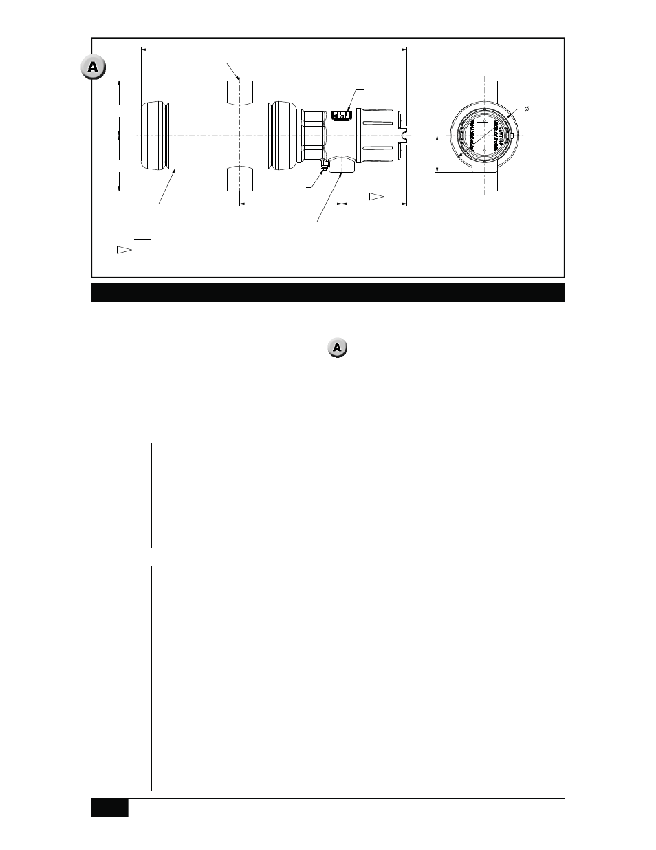
PRODUCT CERTIFICATION DRAWING
ALL DIMENSIONS ARE ±1/16 IN
UNLESS OTHERWISE SPECIFIED
MM
LINEAR =
D
J
CH
M
EN
R
10-32 EXTERNAL
GROUND SCREW
4 IN SCH 40
EXTERNAL CHAMBER
ELECTRICAL CONNECTION
1 NPTF STD
3/4 NPTF OPT
1/2 NPTF OPT
M20 X 1.5 F OPT
2X 1 IN 3000# SW
PROCESS CONNECTION
NAMEPLATE
FRONT VIEW
LEFT SIDE VIEW
1
Installation
Multiple
Switch
Chambers
External switch chambers must be mounted so that the centerline is within 3º of
horizontal. The conduit connection centerline must be within 3° of vertical and the
nameplate at 12 o’clock (facing up - see
). Switch actuation cannot be reversed
by rotating the unit 180°.
Pipe support hangers or stands should be used where necessary.
All isolation valves must be fully open during service, as restricted valves may
cause erroneous level switching.
Single
Switch
Chamber
In addition to the Single Switch installation instructions, multiple chamber
installations have the following requirements:
Headers connecting multiple chambers to the process must be larger
than the chamber process connection diameter to allow adequate liquid
flow to all chambers. Header diameters are listed below:
- Header diameter must be 1.5 times larger than process connection
diameter for two chambers.
- Header diameter must be 2 times larger than process connection
diameter for three or four chambers.
- Header diameter must be 2.5 times larger than process connection
diameter for five or more chambers.
Valves, tees, elbows and other pipe fittings in a header must be the
same diameter as the recommended header diameter.
External chamber piping should be short, straight and unrestricted.
Pipe must be of a diameter equal to or greater than the process
connection diameter.
Valves and other equipment between the chamber and process
must be of the same diameter or larger than the process connection
diameter to allow adequate liquid flow into the chamber.
Dimensions are for reference
only. Contact the factory for
certified drawings for a
particular model number.
Linear = mm/inches
Drawing 0390698
NOTES:
112.8
1. ADD MINIMUM
CLEARANCE
4.44
REQUIRED TO REMOVE HOUSING COVER
1