Max) = v, 8v 20ma – SOR 805PT Pressure Transmitter User Manual
Page 3
Form 1435 (10.13) ©SOR Inc.
3/8
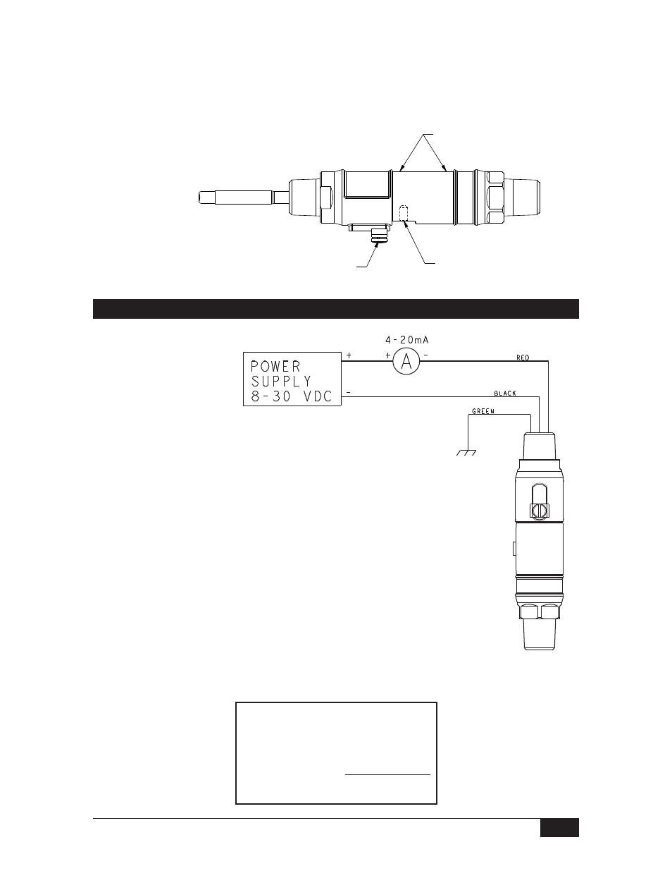
Electrical Termination - 805PT-C
Drawing 0190315
Formula for determining
maximum loop resistance
R
L
(MAX) = V
Supply
- 8V
20mA
72” flying leads are provided for connection to a terminal
strip within a cabinet or a splice within an outlet box:
NOTE: An external ground screw is included for additional earth ground connection.
}
Red
(+)
Loop Voltage: 8 to 30 VDC
Black
(–)
Output: 4 to 20 mA
Blue
(Used for 805PT-V Models Only)
Green Earth Ground
White Calibration
(Requires SOR Calibration Kit)
Brown
Not Used (trimmed at factory)
Bare
Drain Wire - Connected to
Earth Ground (trimmed at factory)
Horizontal Installation
The following figure depicts the proper horizontal installation profile; with the external
ground provision and set screw (annunciation path) oriented downward.
The nameplate (tag) should not cover the set screw.
Align the nameplate slot with the set screw; i.e., the
set screw should be visible in the nameplate slot.
SET SCREW
ANNUNCIATION PATH
NAMEPLATE AREA
EXTERNAL GROUND
PROVISION
- Adjustable Dead Band Explosion Proof Pressure Switch (4 pages)
- 805QS Pressure Switch-Transmitter (8 pages)
- 805PT Pressure Transmitter (12 pages)
- Big Hermet Explosion Proof, Hermetically Sealed, Pressure Switch (8 pages)
- Bourdon Tube Explosion Proof Pressure Switch (4 pages)
- Dual Hi-Lo Explosion Proof Sealed Pressure Switch (4 pages)
- Explosion Proof (8 pages)
- Explosion Proof (4 pages)
- Explosion Proof Pressure Switch UL/CSA/ATEX (8 pages)
- Mini-Hermet (8 pages)
- Mini-Hermet (4 pages)
- Sub Mini Hermet (4 pages)
- Omni Weatherproof Pressure Switch (4 pages)
- Weatherproof Pressure Switch (4 pages)
- Weatherproof Pressure Switch (2 pages)
- 815DT Smart (24 pages)
- 815PT Smart Pressure Transmitter (24 pages)
- 534CR Pressure Transmitter (8 pages)
- 534HS Two-Wire Pressure Transmitters (12 pages)
- 536CR Low Power Pressure Transmitters (8 pages)
- 536HS Low Power Pressure Transmitters (8 pages)
- 510IM Immersible Transmitter (4 pages)
- 503FR Fixed Range Pressure Transmitter (4 pages)
- 101/121 Differential Pressure Switches (12 pages)
- Dual Opposed Diaphragm (12 pages)
- High Static Operation (8 pages)
- High Static Operation (12 pages)
- Low Pressure Switch Low Range Series 20 (8 pages)
- Low Range (4 pages)
- Single Diaphragm (4 pages)
- Big Hermet (12 pages)
- Direct or Remote Mount Explosion Proof UL/CSA/ATEX (8 pages)
- Side Mounted Level Switches (16 pages)
- Flanged Level Switches (4 pages)
- Sealed Level Switches (8 pages)
- 1510 Side Mounted Level Switch (8 pages)
- 1520 Electric Flow Switch (8 pages)
- 1530 Pneumatic Level Switch (4 pages)
- 1540 Side Mounted Non-Bleed Pneumatic Level Switch (4 pages)
- 1550 Top Mounted Level Switch (8 pages)
- 1710 Compact Level Switch (8 pages)
- Multi Point RF Level Switch (36 pages)
- Single Point RF Level Switch (12 pages)
- Single Point RF Level Switch (16 pages)