Installation overview for pull-to-open gates – Mighty Mule FM350 User Manual
Page 16
12
rev 07.16.12
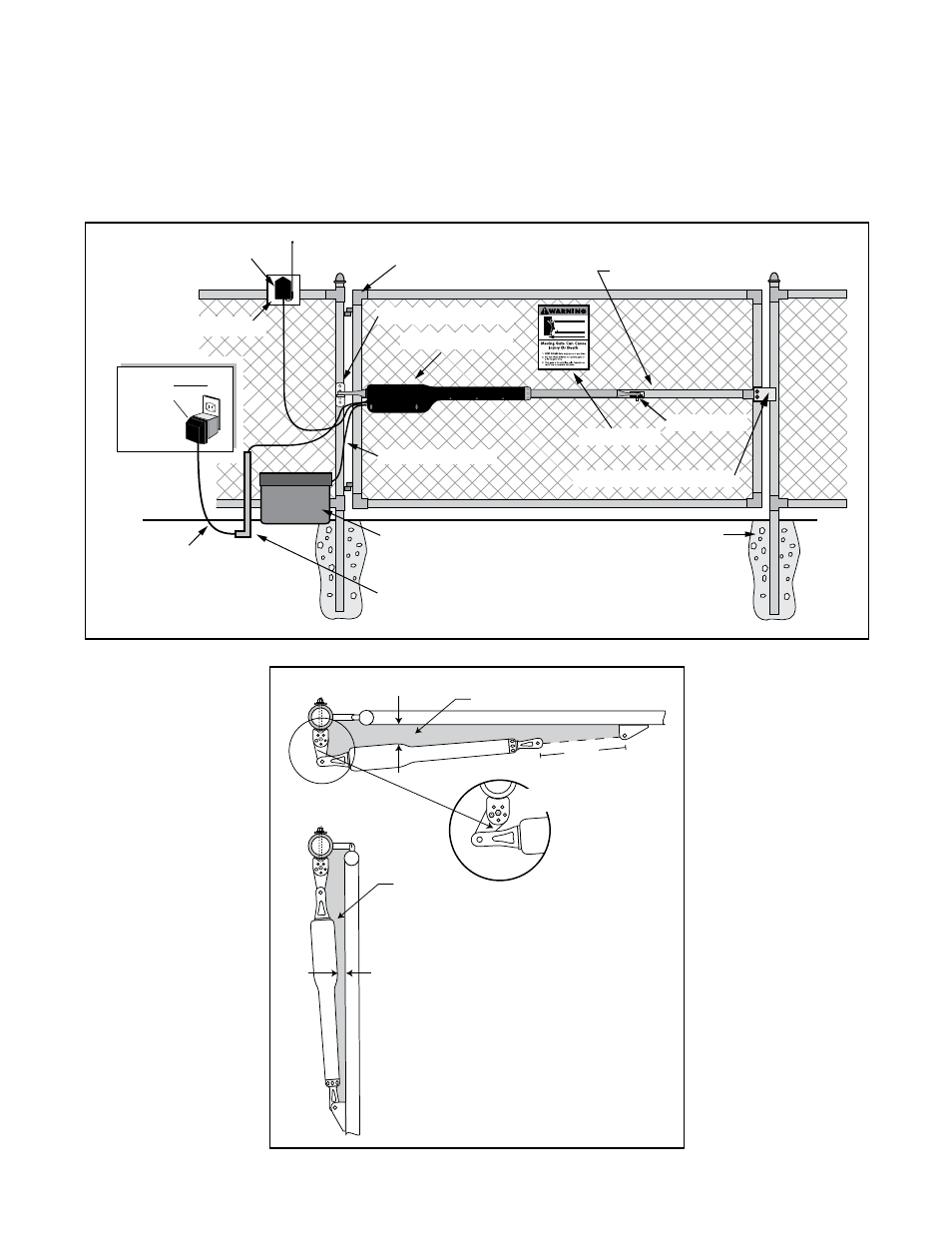
Horizontal Cross Member
Gate Swings Evenly and Freely
Hung Firmly and Plumb
Receiver
Wood Mounting Plate
Post Bracket Assembly
12 Volt automotive or marine
type battery in weather proof
housing (not included).
Gate Bracket
Single Gate Opener
Fence Post Set in Concrete
Run 1000' (max.) of low
voltage wire to control
box from transformer
(wire not included).
10’ Battery Harness
Closed Position Stop Plate
120 Volt indoor
Transformer
(surge protector
not supplied)
PVC conduit (not included)
to protect wire from lawn
mowers and weed eaters.
Warning Sign
Installation Overview for Pull-To-Open Gates
PUSH-TO-OPEN installation instructions begin on page 31.
The diagram shown below is an example of a pull-to-open installation on a chain link fence and single gate.
Mounting the opener on a masonry column requires special procedures; see
Column Installation Information
on page 37 if you intend to mount the opener on a column. Furthermore, if you have a push-to-open gate, you
will need to purchase a
push-to-open bracket [FM148] to properly configure your system. See Push to Open
Installation on page 31 before proceeding.
Gate in the
CLOSED POSITION
Pinch Area
Gate in the
OPENED POSITION
Pinch Area
2" minimum
2" minimum
Be sure gate opener
and bracket don't bind.
19” MAX
TIP:
Turning the pivot
bracket over gives more
hole alignment options
for the post pivot bracket
assembly. You can also
move the entire post
pivot bracket assembly
to different positions
on the gate post to
help achieve the proper
clearances.