Gate operator installation, Top view, Closed position open position – Mighty Mule FM200 User Manual
Page 17
1
rev 07.25.12
1
2
3
5
5
S
V
H
I
Y
X
X
F
M
Q
B
Q
3
1. KEEP CLE
AR! G
ate ma
y mo
ve a
t any tim
e.
2. Do not allo
w c
hildre
n to op
erate g
ate or
play in ga
te area.
3. This gate is
for vehic
les on
ly. Ped
estrian
s
must us
e a se
parate
entra
nce.
Moving Ga
te Can
Cause
Injury O
r Dea
th
WARNING
!
Thin Walled
Tube Gate
Gate
Bracket
1” x 6” Wood Reinforcement
Panel
Gate
Gate
Bracket
Wood or Metal
Reinforcement
(not supplied)
Mounting Plate
Created for
Decorative Gate
(required but not
supplied)
Remove excess bolt length
with hacksaw or bolt cutters
FRONT VIEW
SIDE VIEW
Reinforcement and Gate Bracket Mounting
Muffler Clamp
(not supplied)
Gate
Bracket
1. KEEP CLE
AR! G
ate ma
y mo
ve at
any t
ime.
2. Do not allo
w c
hildre
n to op
erate g
ate or
play in
gate
area.
3. This gate
is for vehic
les on
ly. Ped
estrian
s
must us
e a se
parate
entra
nce.
Moving Ga
te Can
Cause
Injury O
r Dea
th
WARNING
!
2
4
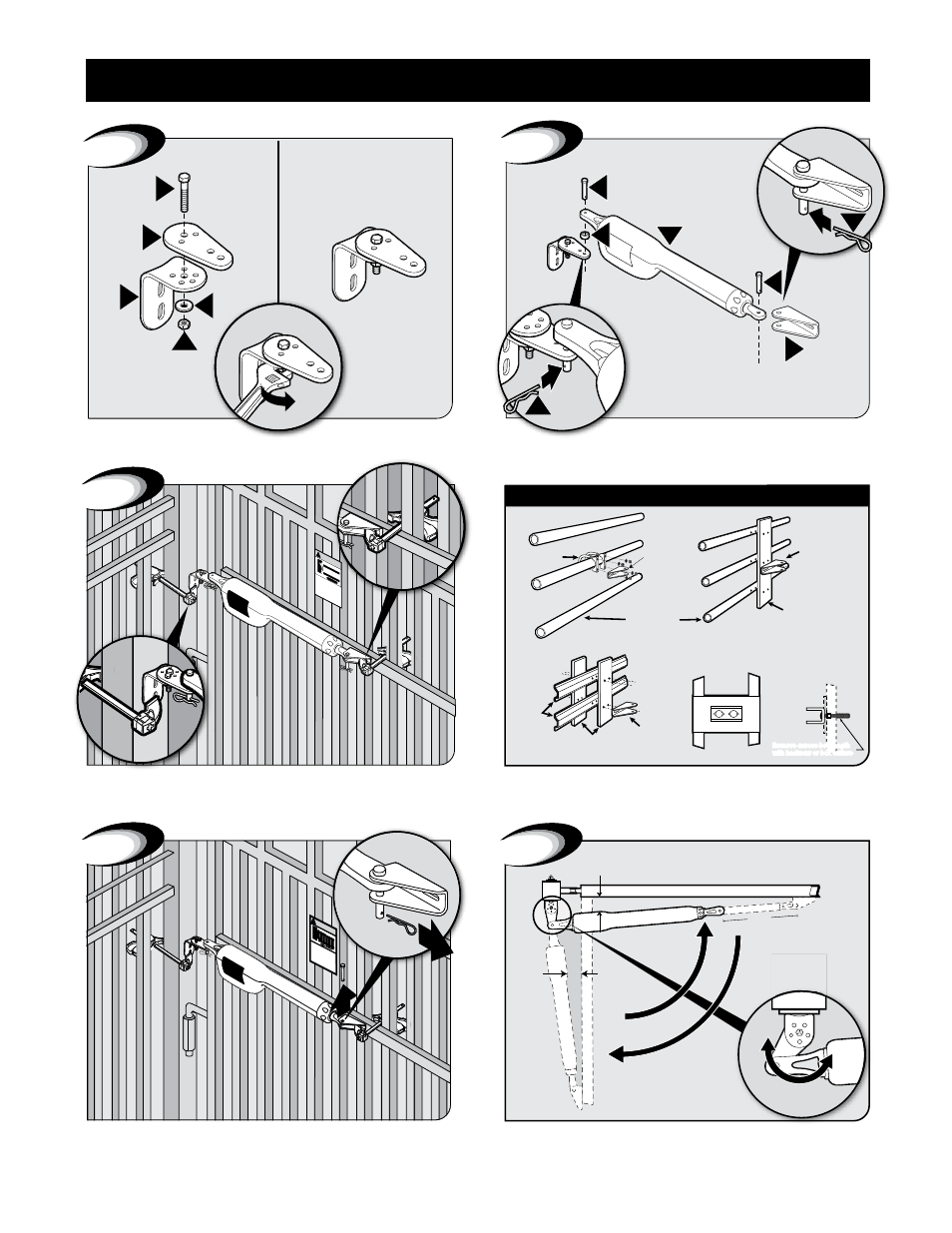
1
1" Min. - Pinch-Point Clearance
Top View
1" Min.
13"
2
1
Closed
Position
Open
Position
Attach opener to gate and post bracket and secure with required
hardware.
Assemble post bracket parts.
With Gate in OPEN position, using clamps, secure opener to gate
post and center cross member of gate.
Recommended reinforcement and gate bracket mounting examples.
Swing gate to
CLOSED position-check clearance/binding by
inspecting alignment. Arm stroke should be minimum of 7” and
13” Max.
TIP: Turning the pivot bracket over gives more hole
alignment options for the post pivot bracket assembly.
Remove clevis pin from the gate bracket and
support loose opener.
GATE OPERATOR INSTALLATION