Martin Christ RVC 2-18 CDplus User Manual
Page 28
RVC 2-18 CD& HCL
5 Set-up and connection
28
Version 04/2012, Rev. 1.4 of 25/11/2013 • sb
Translation of the original operating manual
Pos: 97 / 200 Christ /37 1 RVC-BA (PROJEKTE) /RVC 2-1 8 CDpl us_2 -18 CD plus_HCl /050 Aufstell ung und Anschluss /05 0-0 060 -00 21 S TANDARD: Kond ensa tion übe r ein e Kühlf alle_HCl @ 12\ mod _13 352 559 377 47_ 68.d ocx @ 639 99 @ 3 @ 1
5.5.2
STANDARD: Condensation of the vapours in a glass cooling trap
With a Rotational Vacuum Concentrator 2-18 CD
plus
HCl, a cooling trap
and a glass cooling trap
The characteristic feature of a rotational vacuum concentrator (RVC) is the
combination of vacuum and rotation. During the process, a gas volume is
released. The released vapours that are carried off by the RVC condenser
in the glass cooling trap. This glass cooling trap is located inside a CT 02-
50 SR or CT 04-50 SR cooling trap.
The method is suitable for aqueous and solvent-containing samples. The
RVC, cooling trap, and vacuum pump are connected with each other. The
electromagnetic stop valve is also connected to the RVC and its connector
is plugged into the "stop valve" socket.
An aeration valve can be installed between the vacuum pump and cooling
trap. It ensures the aeration, and facilitates the removal of the glass cooling
trap.
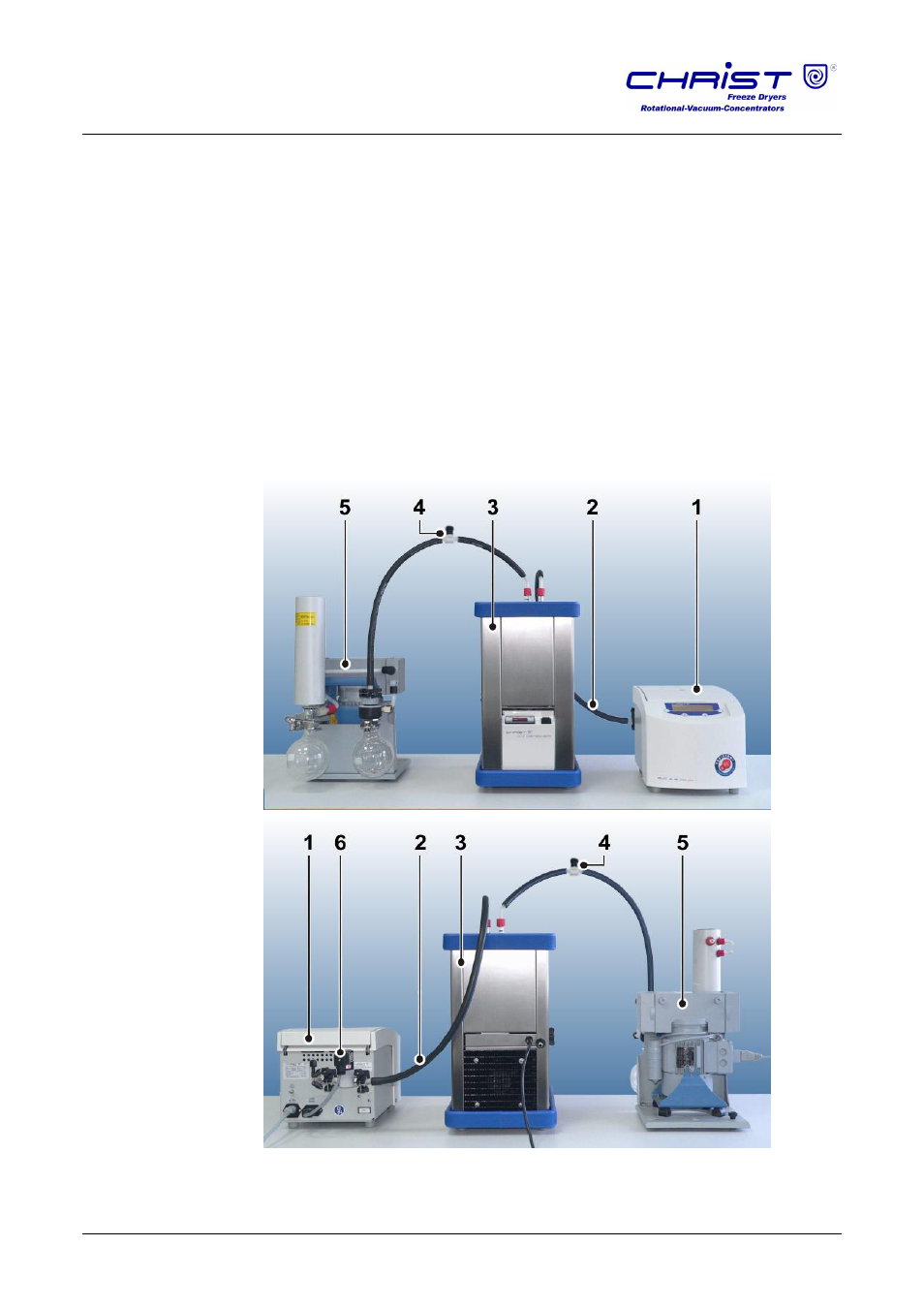
1
RVC
2
Vacuum hoses
3
Cover with connecting
hoses
4
Aeration valve
(manual)
5
Vacuum pump
6
Electromagnetic stop
valve
Fig. 8: Combination of the RVC with vacuum pump and cooling trap, front and rear view
Pos: 98 / 010 Unive rsalm odul e/ Seit enwec hsel @ 0\m od_ 120 211 6244 312 _0. docx @ 10 5 @ @ 1