3 aeration valve, 4 vacuum connections – Martin Christ RVC 2-18 CDplus User Manual
Page 26
RVC 2-18 CD& HCL
5 Set-up and connection
26
Version 04/2012, Rev. 1.4 of 25/11/2013 • sb
Translation of the original operating manual
Pos: 89 / 200 Christ /37 0 RVC-BA (STANDARDM ODULE)/ 050 Au fstellu ng u nd Ans chluss/ 050 -00 30 B elüftu ngsv entil @ 8\m od_ 130 941 9388 700 _68 .docx @ 4 6708 @ 3 @ 1
5.3 Aeration valve
The RVC is equipped with an electromagnetic aeration valve. The rotor
chamber is aerated through this valve after the end of the evaporation
process.
NOTE
Unpressurised inert gas can also be used for aerating the rotor chamber.
Pos: 90 / 010 Unive rsalm odul e/ L ee rzeile @ 0\ mod _120 211 624 450 0_0. docx @ 11 4 @ @ 1
Pos: 91 / 200 Christ /37 1 RVC-BA (PROJEKTE) /RVC 2-1 8 CDpl us_2 -18 CD plus_HCl /050 Aufstell ung und Anschluss /05 0-0 041 Vaku umve rbin dun gen HCl @ 1 2\mo d_1 335 427 492 160 _68. docx @ 64 082 @ 3 @ 1
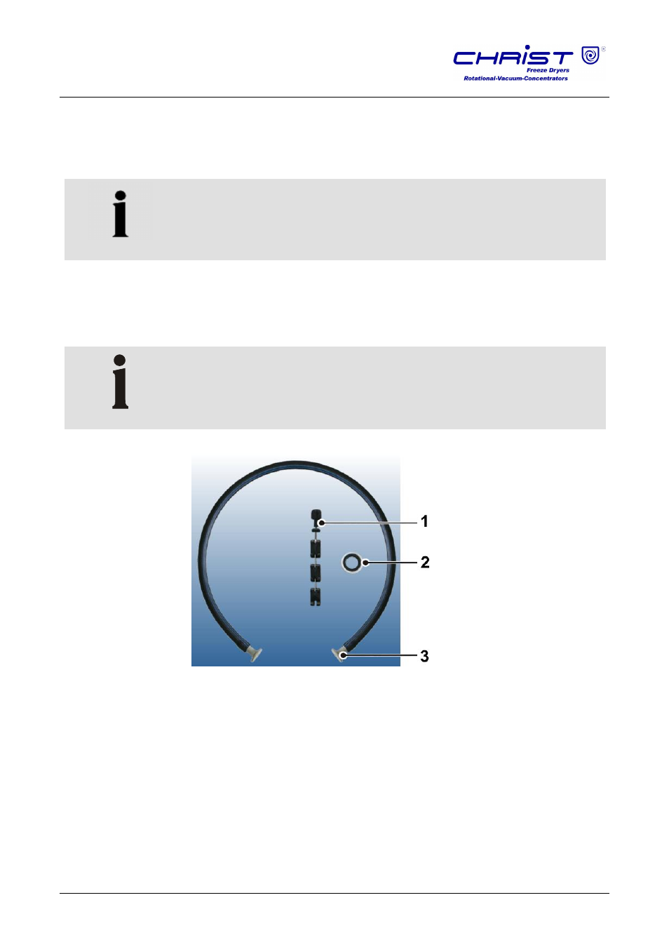
5.4 Vacuum connections
The vacuum connection is realised by way of a vacuum hose with standard
flange connections, clamping rings, or chains, and centring rings.
NOTE
The small flange connections must be installed correctly in order to
prevent leaks.
1
Clamping chain
2
Centring ring
3
Flange connection
Fig. 2: Connecting pieces for vacuum connections
Pos: 92 / 010 Unive rsalm odul e/ Seit enwec hsel @ 0\m od_ 120 211 6244 312 _0. docx @ 10 5 @ @ 1