6 vacuum pump, 7 pressure control valve – Martin Christ Alpha 2-4 LSCplus User Manual
Page 34
ALPHA 1-4 LSC&
ALPHA 2-4 LSC&
5 Set-up and connection
34
Version 01/2011, Rev. 1.5 of 16/12/2013 • sb
Translation of the original operating manual
Pos: 106 /20 0 Ch rist/3 61 G T-BA L abo r-Pilot (PROJEKTE)/Alph a 1 -4_ 2-4 LSCplus/ 050 A ufstellu ng und An schluss/ 050 -00 60 Vakuu mpu mp e Alpha @ 5\ mo d_12 980 253 349 68_ 68.d ocx @ 338 65 @ 2 @ 1
5.4.6
Vakuum pum pe
5.6 Vacuum pump
NOTE
Please refer to the separate operating manual of the vacuum pump and
the exhaust filter!
The vacuum pump must be connected to the vacuum connector of the unit
and its plug must be plugged into the IEC C14 connector on the back of the
unit (see chapter 2.1.1 - "Functional and operating elements").
The oil mist that escapes when the pump is in operation must be retained
or carried off by way of an oil mist separator.
• We recommend using an oil mist separator. This filter prevents air
pollution by oil mist.
• In order to carry off the oil mist, connect a suitable hose to the exhaust
port of the vacuum pump (RZ-2.5 and RC-6: ½", DUO 5 or DUO 10 ¾").
• The hose must be laid so that the condensate cannot flow back into the
pump. In the case of upward leading hoses, we recommend using a
separator (Woulfe's bottle or wash bottle).
Pos: 107 /01 0 Univ ersal mod ule/ Lee rzeile @ 0\ mo d_12 021 162 445 00_ 0.doc x @ 1 14 @ @ 1
Pos: 108 /20 0 Ch rist/3 61 G T-BA L abo r-Pilot (PROJEKTE)/Alph a 1 -4_ 2-4 LSCplus/ 050 A ufstellu ng und An schluss/ 050 -00 70 Druck steu erve ntil Alph a @ 5 \mo d_1 298 025 5268 43_ 68. docx @ 33 872 @ 2 @ 1
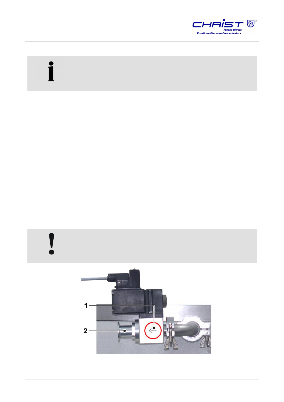
5.7 Pressure control valve
The pressure control valve is integrated in the suction pipe between the
vacuum pump and ice condenser chamber. During certain, specified
process phases, it interrupts the volume flow to the vacuum pump (see
chapter 2.2.1 - "General information on freeze-drying").
CAUTION
Observe the installation direction of the pressure control valve!
1
Pressure control valve
2 Vacuum pump
connection
Fig. 16: Installation of the pressure control valve
Pos: 109 /01 0 Univ ersal mod ule/ Ab schnitt swechs el @ 0 \mo d_1 202 124 514 062_ 0.d ocx @ 418 @ @ 1
Pos: 110 /01 0 Univ ersal mod ule/ Sei tenwe chsel @ 0\ mod _12 021 1624 431 2_0 .docx @ 1 05 @ @ 1