3 aeration valve, 4 media drain valve, 5 vacuum sensor – Martin Christ Alpha 2-4 LSCplus User Manual
Page 32
ALPHA 1-4 LSC&
ALPHA 2-4 LSC&
5 Set-up and connection
32
Version 01/2011, Rev. 1.5 of 16/12/2013 • sb
Translation of the original operating manual
Pos: 100 /20 0 Ch rist/3 61 G T-BA L abo r-Pilot (PROJEKTE)/Alph a 1 -4_ 2-4 LSCplus/ 050 A ufstellu ng und An schluss/ 050 -00 30 Belüft ungsv entil @ 5\m od_ 129 802 477 345 3_68 .docx @ 3 384 4 @ 2 @ 1
5.3 Aeration valve
The aeration valve is located on top of the left side of the unit. After the end
of a freeze-drying process, the unit will be aerated via the aeration valve.
Pos: 101 /01 0 Univ ersal mod ule/ Lee rzeile @ 0\ mo d_12 021 162 445 00_ 0.doc x @ 1 14 @ @ 1
Pos: 102 /20 0 Ch rist/3 61 G T-BA L abo r-Pilot (PROJEKTE)/Alph a 1 -4_ 2-4 LSCplus/ 050 A ufstellu ng und An schluss/ 050 -00 40 Me dien ablau fventil @ 5\ mod _12 980 248 587 50_ 68.d ocx @ 338 51 @ 2 @ 1
5.4 Media drain valve
The media drain valve is located at the bottom of the left side of the unit. It
is used to drain off the condensate and the defrosting water.
• Connect the drain hose (included in the scope of supply) to the hose
connector.
• Place a collecting vessel under the unit.
The hose must be laid with a continuous slope and the end of the hose
must always be above the liquid level in the collecting vessel. This prevents
water and dirt residues from being sucked into the ice condenser chamber
if there is negative pressure when the media drain valve is opened.
Pos: 103 /01 0 Univ ersal mod ule/ Lee rzeile @ 0\ mo d_12 021 162 445 00_ 0.doc x @ 1 14 @ @ 1
Pos: 104 /20 0 Ch rist/3 61 G T-BA L abo r-Pilot (PROJEKTE)/Alph a 1 -4_ 2-4 LSCplus/ 050 A ufstellu ng und An schluss/ 050 -00 50 Vakuu mm essso nde Alp ha @ 5\m od_ 129 802 497 728 1_68 .docx @ 3 385 8 @ 2 @ 1
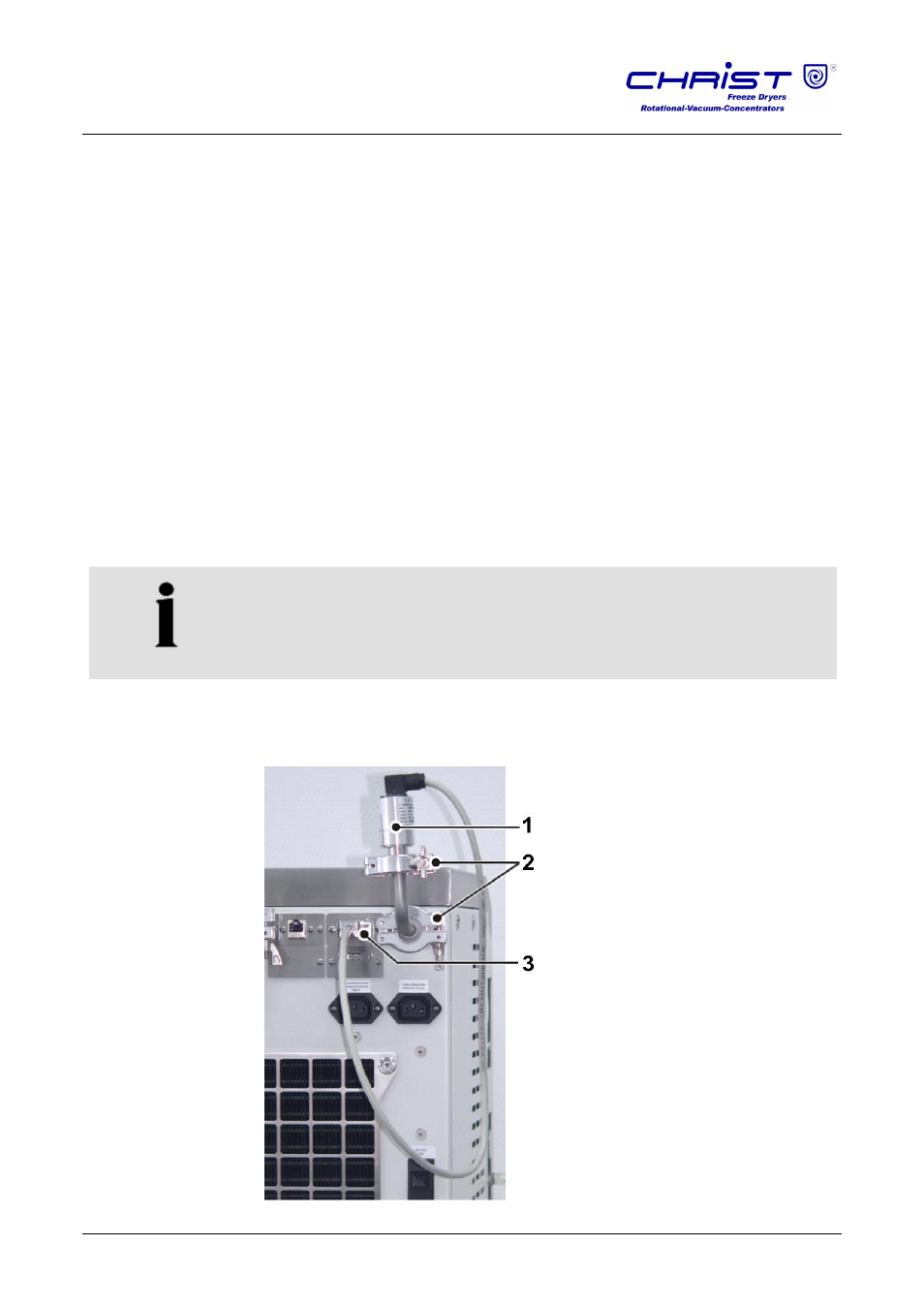
5.5 Vacuum sensor
NOTE
Please refer to the separate operating manual of the vacuum sensor!
In order to protect the vacuum sensor against transport damage, it comes
supplied in its original packaging. Prior to commissioning the freeze-dryer,
the sensor must be installed.
1
Vacuum sensor
2
Clamping rings
3
Connection socket
Fig. 14: Position of the vacuum sensor and the connection socket