Lnc-2000 timing retard activation (cont...) – Lingenfelter L460145297 Lingenfelter LNC-2000 LS Timing Retard Launch Controller v2.0 User Manual
Page 24
Page 23 of 31
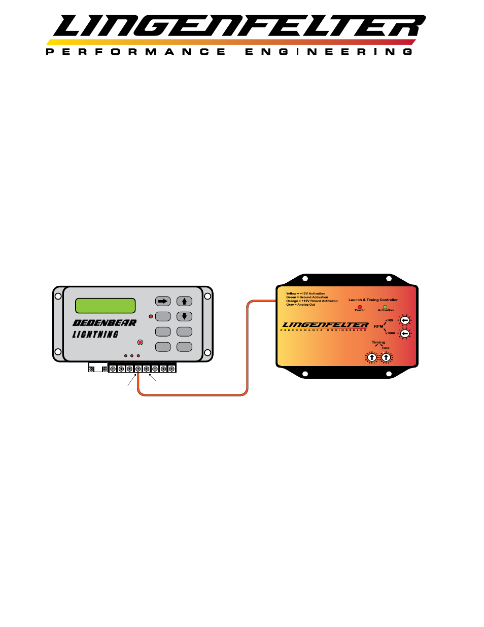
LNC-2000 Timing Retard Activation (Cont...)
LNC-2000 Receiving +12V Retard Activation Input from the
Dedenbear Lightning Delay Box
Use this wiring configuration to allow a Dedenbear Lightning (L1 or L2) or Command Center 3 (CC-3)
Delay Box to control the +12V retard activation for the LNC-2000.
• The +12V retard activation (orange) wire can be connected to either the Throttle Stop A or Throttle
Stop B output on the Dedenbear Delay Box.
• The output from the delay box should be configured for two timers with the first timer being set to
zero and the second timer being set to the point in time where timing should no longer be pulled.
• It is important to note that the location of the Throttle Stop A and Throttle Stop B terminals on the
terminal barrier strip is different depending on the Dedenbear Delay Box model that you are using.
Refer to your delay box installation instructions for the location of these terminals.
LNC-2000
Red = MAP +5V
Black = MAP/Linear Ground
Purple = MAP/Linear Signal
F
= Linear Mode
.2 Volt = 0*
4.8 Volt = 15*
Max Retard
STOPA
STOPB
RSET
TBRK
MODE
A B TB
P/F
Throttle Stop B
Throttle Stop A
+12V LNC-2000 Retard
Activation Input (Orange)
The Dedenbear Lightning Delay Box is
property of Dedenbear Products Inc.