Manual transmission with linelock & nitrous, Page 15 of 31, 12v fuse 5 amp – Lingenfelter L460145297 Lingenfelter LNC-2000 LS Timing Retard Launch Controller v2.0 User Manual
Page 16: Ground
Page 15 of 31
LNC-2000
Red = MAP +5V
Black = MAP/Linear Ground
Purple = MAP/Linear Signal
F
= Linear Mode
.2 Volt = 0*
4.8 Volt = 15*
Max Retard
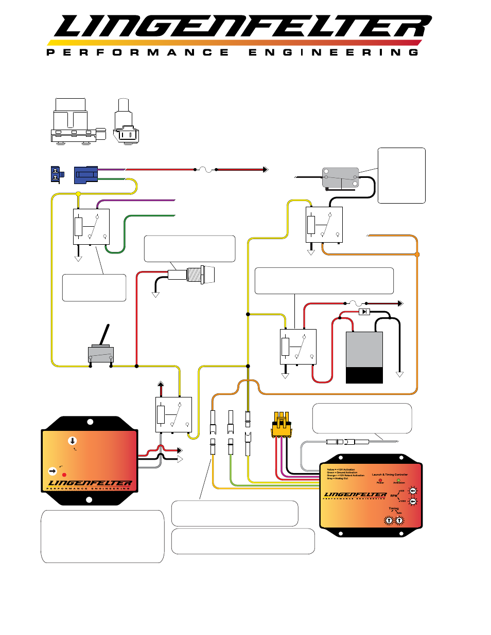
Manual Transmission with Linelock & Nitrous
A
B
C
1
1 - Locate CPP (Clutch Position Switch) and unplug 2-wire connector.
2 - Cut wires appox. 3" back from connector.
3 - Find +12 volt Key On power source and connect to one wire of CPP connector.
4 - Splice two wires onto remaining CPP connector wire and connect one wire to #85 on Relay.
The extra wire will be used for LNC-2000 Launch Controller activation.
5 - Connect terminal #86 on Relay to Ground.
6 - Connect wires cut from CPP Switch connector to Terminals #30 and #87 as shown.
Wire color illustrated is
for 1999 TransAm
+12V
Fuse
5 Amp
85
86
30
87a
87
2
3
6
4
Ground
5
Connect wires cut from CPP
Switch connector in Step 2
to Relay as shown.
General purpose
Automotive Relay.
5 to 40 Amp
Toggle Switch
Arms Linelock
and 2-Step
Ground
85
86
30
87a
87
Ground
Linelock
Solenoid
+12V
Ground
Optional LED, On when
Arming Switch is ON and
Clutch Pedal is depressed.
Relay can be omitted if Linelock Solenoid
has a lower current/amp draw than the
Momentary Switch rating.
Analog Output
0-3 volt, .2 volt per 1* of Retard
Connect to analog input of Data
Recorder.
Retard Activation Connect to Nitrous
WOT switch signal or to +12V output
from Nitrous controller.
85
86
30
87a
87
Ground
To Nitrous Relay
When the LNC-2000 is powered up with no
MAP Sensor installed it will default to
Time Based Retard mode.
Use this wiring configuration to simultaneously activate the 2-step feature and linelock
using the Clutch Switch and the STOV-002 MPH activated switch. The STOV-002 should
be set so that after the vehicle launches from the line, the 2-step feature and linelock
gets disabled while the nitrous is enabled and is controlled by a WOT switch.
0
1
3
5
6
7
2
4
8 9
A
B
C
D
E
F
0
1
3
5
6
7
2
4
8
9
A
B
C
D
E
F
Power
STOV-002
Speed to Voltage
Ground - Black
Stage Out / Norm On - Gray
Activation Out / Norm Off - Green
PPM Signal Input - White
Co
Conv
nve
errtor
tor
Function Selection
Range Selection
+12V Switched Power - Red
Voltage Out - Yellow
85
86
30
87a
87
Ground
+12V
+12V
The STOV-002 is used to eliminate
the possibility of the linelock being
inadvertently re-engaged while the
vehicle travels down the track. The
STOV-002 should be set to a vehicle
speed below the first shift point.
TVS
diode
WOT switch
or
CTAP-001 on
throttle signal
or
Nitrous
controller