Lingenfelter L460145297 Lingenfelter LNC-2000 LS Timing Retard Launch Controller v2.0 User Manual
Page 11
Note about manual transmission clutch switch/position sensor on GM vehicles:
• On manual transmission vehicle applications please note that most GM vehicles have two switches
on the clutch pedal. One is the cruise control disable switch at the top of the travel and the other is
the neutral safety/starter enable clutch switch at the bottom of the travel. In testing LPE has found
that the upper clutch switch (cruise control switch) has erratic output and causes improper operation
of the LNC. For this reason, the lower clutch switch is the switch that should be used to trigger the
LNC. The problem, however, is that the lower clutch switch is powered by a circuit that is only
energized while the vehicle is cranking. For the LNC to work with the lower clutch switch, a relay
must be added before the switch in order for the switch to be powered while the vehicle is running.
Refer to the clutch switch wiring diagram on page 12 for instructions on how to modify the circuit
correctly. Another alternative is to mount a separate microswitch to the pedal assembly and activate
from that. LPE offers a microswitch kit, PN L480330000.
• On many newer vehicles GM has replaced the two clutch position swithces with a single clutch
pedal position (CPP) sensor with an analog 0-5 volt output that provides the ECM with clutch pedal
position information over the entire pedal travel. This sensor is similar to a throttle position sensor
except that the output of this sensor is from high to low. Because it is not a switched (ON/OFF) type
output, the CPP sensor can’t be used to trigger the LNC or a relay directly. LPE has developed the
CTAP-001 module (PN L460190108) that can read the CPP sensor and provides a user adjustable
switched output based on the clutch pedal position. Vehicles with the CPP sensor include the 2008-
2013 Corvette, 2010-2014 Camaro and 2009-2014 CTS-V.
Nitrous, line-lock, trans-brake and other solenoid usage warning:
LPE has found that these solenoids can cause fly-back voltage levels at times in excess of 600 volts.
These voltage levels have the potential to damage sensitive electronics including the LNC-2000, the
PCM/ECM and other modules in the vehicle. LPE has developed a transient voltage suppression
(TVS) diode kit (PN L450080000) for use with line-lock solenoids, trans-brake solenoids and other
aftermarket automotive solenoids of this type. The TVS diode is a special kind of diode used to supress
voltage spikes. LPE recommends the use of our TVS diode on all vehicles that have a line lock or trans-
brake. This kit comes with three TVS diodes, enough for most common installations. If you have a
vehicle with multiple solenoids we recommend obtaining additional TVS diodes for those solenoids.
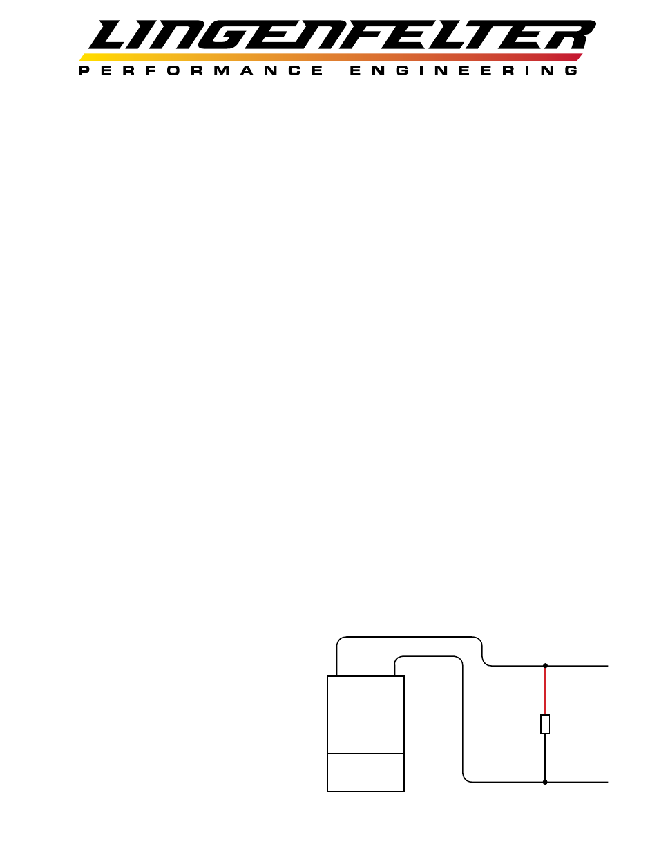
Install the TVS diode across the solenoid wires as close to the solenoid as possible. Polarity does not
matter (Red and Black wires can go to either solenoid wire). If there is no accessible ground terminal to
connect the diode to, such as the case with a trans-brake solenoid, the diode should be connected to the
nearest ground source. In the case of the diode
for the trans-brake solenoid, the diode should
be connected to the transmission case as it will
provide a ground path.
LPE recommends using TVS diodes on:
• Nitrous solenoids
• Nitrous purge solenoids
• Fuel solenoids
• Line-lock solenoids
• Trans-brake solenoids
Page 10 of 31
Solenoid
TVS
diode