Installation – Labconco Protector Controlled Atmosphere Glove Boxes 5080102 User Manual
Page 15
INSTALLATION
16
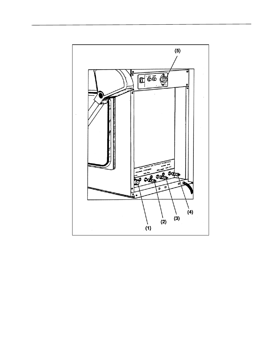
Figure 7
Gas and vacuum connections are illustrated for the various models in Figures 8, 9 and 10.
The illustrations show connections for models as follows: Figure 8 depicts Models 506000000 and
506010000, Figure 9 depicts Models 507000000 and 507010000, Figure 10 depicts Models
508000000 and 508010000.
This manual is related to the following products:
- Protector Controlled Atmosphere Glove Boxes 5070102 Protector Controlled Atmosphere Glove Boxes 5060102 Protector Controlled Atmosphere Glove Boxes 5080100 Protector Controlled Atmosphere Glove Boxes 5070100 Protector Controlled Atmosphere Glove Boxes 5060100 Protector Controlled Atmosphere Glove Boxes 5080002 Protector Controlled Atmosphere Glove Boxes 5070002 Protector Controlled Atmosphere Glove Boxes 5060002 Protector Controlled Atmosphere Glove Boxes 5080000 Protector Controlled Atmosphere Glove Boxes 5070000 Protector Controlled Atmosphere Glove Boxes 5060000