Testing and maintenance – IOTA EM1 Dual Head Emergency Fixture User Manual
Page 2
Page 2
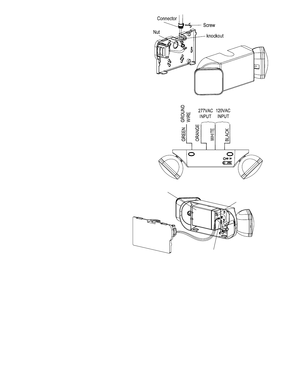
Fig. 2
Fig. 3
Fig. 4
1. Mounting (cont.)
For CEILING MOUNTING, Remove the mounting plate
from the fixture by pressing on the pressure pads on the
bottom of the unit. Remove the top knockouts on both
the mounting plate and the top of the fixture. Secure the
mounting plate to the rigid electrical conduit using a screw,
pipe connector, and nut (not provided).
See Fig. 2
2. Electrical Connections
A) Connect the WHITE wire lead from the fixture to the
NEUTRAL wire supply feed from the circuit. Con-
nect either the BLACK (120V) or ORANGE (277V),
depending on supply voltage, to the BLACK (Hot)
wire from the supply circuit.
See Fig. 3. Use only UL
Listed wire connectors suitable for the size, type,
and number of conductors. CAP ALL UNUSED
LEADS. No loose strands or uncapped wires should
be present. Secure wire connectors with UL Listed
electrical tape.
B) Connect the transformer to the PCB Assembly, as
shown
in Fig. 4
C) Connect the spade connector of the RED Lead to
the battery’s POSITIVE (red) terminal (
Fig. 4).
3. Completing Installation
Snap the fixture onto the mounting plate and ensure no
wires are pinched. Make sure the unit is fully and firmly
attached.
Restore AC power. The AC indicator on the fixture
will be lit. To test the unit, press the test button. The
battery-powered lamps will come on and the AC Indi-
cator will turn off.
Testing and Maintenance
Pressing the Test Button turns off the AC Indicator light and forces the unit into emergency mode and activates the
lamps. After releasing the Test Button, the fixture returns to normal operation.
Initial Testing – Allow the unit to charge approximately 1 hour, then press the test switch to conduct a short discharge
test. Allow a 24 hour charge before conducting a one hour test.
This is a maintenance free unit, however, periodic inspection and testing is required. NFPA 101, Life Safety Code, out-
lines the following schedule:
Monthly – Insure that the AC indicator is illuminated. Conduct a 30 second discharge test by depressing the Test Button.
The lamps on the unit should be lit.
Annually – Insure that the AC indicator is illuminated. Conduct a full 1
1
/
2
hour discharge test. The unit should operate as
intended for the duration of the test.
“Written records of testing shall be kept by the owner for inspection by the authority having jurisdiction.”
SERVICING SHOULD BE PERFORMED BY QUALIFIED PERSONNEL.
Contact Customer Service or visit www.iotaengineering.com for current warranty information.
BATTERY
CONNECT TRANSFORMER
TO PCB ASSEMBLY
CONNECT RED LEAD
FROM PCB ASSEMBLY TO
BATTERY TERMINAL
68901-000 REV 1400