Testing and maintenance, Mounting – IOTA PE Series User Manual
Page 2
Page 2
Fig. 3
Fig. 4
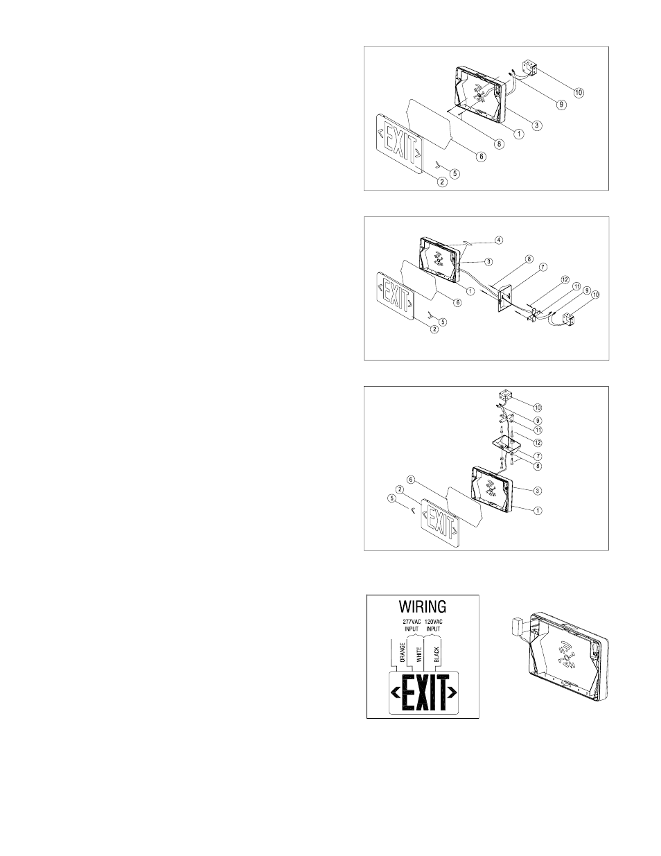
2. Mounting
Back Mounting (Fig 3)
1) Drill 1/4
″ holes into oblong knockouts on backplate (3) that
correspond to juncton box (10) holes to be used.
2) Feed the transformer input leads through the hole and make
the proper connections (refer to Fig 6). Cap all unused leads. If
the unit includes a battery, snap the battery connectors togeth-
er (Fig 7).
3) Feed excess wiring into the junction box and secure the
backplate (3) to the junction box (10).
4) Snap in arrows (5) on EXIT panel (2) if required, then snap
EXIT panel (2) to housing, top first and then bottom.
Testing and Maintenance
Pressing the Test Button turns off the AC Indicator light and
forces the unit into emergency mode and activates the lamps.
After releasing the Test Button, the fixture returns to normal
operation.
Initial Testing – Allow the unit to charge approximately 1 hour,
then press the test switch to conduct a short discharge test. Al-
low a 24 hour charge before conducting a one hour test.
This is a maintenance free unit, however, periodic inspection
and testing is required. NFPA 101, Life Safety Code, outlines the
following schedule:
Monthly – Insure that the AC indicator is illuminated. Conduct
a 30 second discharge test by depressing the Test Button. The
lamps on the unit should be lit.
Annually – Insure that the AC indicator is illuminated. Con-
duct a full 1
1
/
2
hour discharge test. The unit should operate as
intended for the duration of the test.
Fig. 5
Side and Ceiling Mounting (Figs 4 and 5)
1) Attach crossbar (11) to junction box (10). Set the crossbar so
that the longer blade is touching the junction box.
2) Remove the back panel and feed the transformer input leads
through the hole (side or top depending on location of junction
box), being sure to secure wire into wire guides molded at the
edge of the sign.
3) Attach and lock the canopy (7) to the sign by inserting the
canopy (7) into the housing slot at a 20° angle and twisting into
place.
4) Make the proper connections (refer to Fig 6). Cap all unused
leads. If the unit includes a battery, snap the battery connectors
together (Fig 7).
4) Feed excess wiring into the junction box and align holes in
canopy (7) with those in crossbar (11). Using the screws pro-
vided, tighten canopy to crossbar so that canopy is securely
fastened and tight against the wall.
5) Snap in arrows (5) on EXIT panels (2) if required, then snap
EXIT panels (2) to housing, top first and then bottom.
GREEN
GR
O
UN
D
WI
RE
“Written records of testing shall be kept by the owner for inspection by the authority having jurisdiction.”
SERVICING SHOULD BE PERFORMED BY QUALIFIED PERSONNEL.
Contact Customer Service or visit www.iotaengineering.com for current warranty information.
Fig. 6
Fig. 7
68903-000 REV 1400