Iis-375-led-dr wiring connections – IOTA IIS-375-LED-DR User Manual
Page 3
Page 3
E. ALTERNATE FEED (all fixtures are supplied on normal from an alternate circuit) - Follow Step 2B above. Then extend alter-
nate AC input to the proper voltage flying leads from the heatsink assembly (BLACK for 120V, ORANGE for 277V). If a local
Switch is present, connect the alternate AC input to the Switch, then connect the proper voltage flying leads from the heatsink
assembly to the load side of the Switch as in Step 2D. Refer to
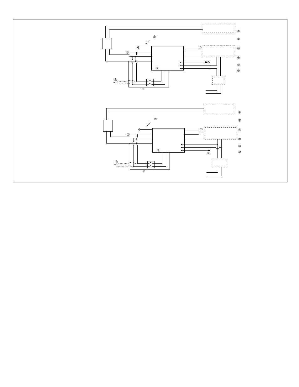
Diagrams 1 and 2.
F.
DIMMING RELAY - The IIS-375-LED-DR features a dimming relay for use with dimming applications. The BLUE (Nor-
mally Open), RED (Common), BROWN (Normally Closed) leads are provided for connection to the dimming circuit.
Refer to the specifications of the dimming controls for proper wiring connections.
G. Connect the Fixture Supply Ground to the
IIS-375-LED-DR Ground.
H. The
IIS-375-LED-DR includes an internal circuit breaker. Push the circuit breaker switch to the ‘closed’ position so that
the indicator on the circuit breaker shows RED. The circuit breaker is located near and slightly above the transformer. If
no circuit breaker is present on your inverter model, then disregard.
Consult
the
IIS-375 Application Notes for connecting the unit to specific lighting loads. Application Notes are available on
the internet or through Customer Service.
CAUTION: Before proceeding to Wiring Step 3, make sure that all unused wires are properly capped. Failure to do
so may result in an unsafe condition and equipment failure.
DO
NOT ENERGIZE THE CIRCUIT AT THIS TIME.
3. INSTALLING THE BATTERY
ATTENTION:
Use only battery part number
F743750001 with the unit. See Page 1 of this instruction manual.
A. Before installing the battery, check the torque on the hardware that connects the polarized connector to the terminals
as these connections may have loosened in transit and storage. The proper torques should be 70 in/lbs for a
Screw
Stud terminal, and 65 in/lbs for an L Flag terminal.
B. Install the battery into the IIS-375-LED-DR with the terminal posts facing toward the front of the unit. NOTE: The
IIS-375-LED-DR battery is heavy. To avoid injury, exercise caution when handling the battery.
C. Plug the battery connector together.
Note: Neither the indicator lights nor the emergency fixtures will illuminate at this time. Also, please note that
there are 2 battery tie down lugs in the event that it is required that the battery be held in place. Please contact
IOTA Engineering Customer Service to purchase this accessory if needed.
IIS_375_550_DR.EPS
INVERTER - INTERRUPTIBLE WITH DIMMER BYPASS
120V
277V
LOCAL SWITCH
(IF PRESENT)
ALTERNATE
AC INPUT
INVERTER
WHT (NEUTRAL)
ORG (277V)
BLK (120V)
FLYING LEADS
GROUND
WIRE
YELLOW (277V)
VIOLET (120V)
GRAY (NEUTRAL)
GREEN
NORMAL CIRCUIT
EMERGENCY CIRCUIT
NORMAL
LIGHTING LOAD
DESIGNATED
EMERGENCY LOAD
INPUT
LEADS
VIOLET
BLK (120V
)
WHT (NEU)
OUTPUT
LEADS
BRANCH
CIRCUIT
OPERATES IN BOTH NORMAL AND
EMERGENCY MODES. CIRCUIT MUST BE
ISOLATED FROM NORMAL CIRCUITS.
BLU (NORMALLY OPEN)
RED (COMMON)
BRN (NORMALLY CLOSED)
DIMMER
CONTROL
DIMMING
RELAY
LEADS
PRIMARY
UNSWITCHED
INPUT
GRA
Y
VIOLE
T
GRA
Y
ORG (277V
)
The Dimming Relay contacts provide electrical continuity during normal power conditions allowing your dimming signal to
operate the luminaire in the desired, dimmed state. When the inverter transfers into the emergency mode, the dimming
relay contacts electrically open the 0-10 dimming reference signal forcing the luminaire to operate at full lumen output
regardless of dimmer setting.
SELECT PROPER VOLTAGE LEAD
AND CAP UNUSED LEAD.
GROUND WIRE - CONNECT FIXTURE SUPPLY
GROUND AND UNIT GROUND IN ACCORDANCE
WITH LOCAL AND NATIONAL CODES.
IF USING A SECONDARY AC INPUT,
SELECT PROPER VOLTAGE LEAD AND CAP
UNUSED LEAD.
USE A 277V RATED SWITCH IF
CONNECTING TO 277V INPUT.
FLYING LEADS - SELECT PROPER VOLTAGE
LEAD AND CAP UNUSED LEAD.
CAP UNUSED LEAD.
IIS-375-LED-DR Wiring Connections
Diagram 1 - Dimmer Bypass
The Dimming Relay contacts provide
electrical continuity during normal
power conditions allowing your dim-
ming signal to operate the luminaire in
the desired, dimmed state. When the
inverter transfers into the emergency
mode, the dimming relay contacts
electrically open the 0-10 dimming
reference signal forcing the luminaire
to operate at full lumen output regard-
less of dimmer setting.
IIS_375_550_DR.EPS
INVERTER - INTERRUPTIBLE WITH EMERGENCY DIMMING SIGNAL
120V
277V
LOCAL SWITCH
(IF PRESENT)
ALTERNATE
AC INPUT
INVERTER
WHT (NEUTRAL)
ORG (277V)
BLK (120V)
FLYING LEADS
GROUND
WIRE
YELLOW (277V)
VIOLET (120V)
GRAY (NEUTRAL)
GREEN
NORMAL CIRCUIT
EMERGENCY CIRCUIT
NORMAL
LIGHTING LOAD
DESIGNATED
EMERGENCY LOAD
INPUT
LEADS
VIOLET
BLK (120V
)
WHT (NEU)
OUTPUT
LEADS
BRANCH
CIRCUIT
OPERATES IN BOTH NORMAL AND
EMERGENCY MODES. CIRCUIT MUST BE
ISOLATED FROM NORMAL CIRCUITS.
BLU (NORMALLY OPEN)
RED (COMMON)
BRN (NORMALLY CLOSED)
DIMMER
CONTROL
DIMMING
RELAY
LEADS
PRIMARY
UNSWITCHED
INPUT
GRA
Y
VIOLE
T
GRA
Y
ORG (277V
)
The Dimming Relay contacts are electrically open during normal power conditions allowing your dimming signal to operate the
luminaire in the desired, dimmed state. When the inverter transfers into the emergency mode, the dimming relay contacts electrically
short the 0-10 dimming reference signal forcing the luminaire to operate at a reduced lumen output setting based on the dimmable
driver being used. Verify operating results of the luminaire with the 0-10 volt reference signal shorted to assure the application and
mounting height produce code-compliant egress lighting.
SELECT PROPER VOLTAGE LEAD
AND CAP UNUSED LEAD.
GROUND WIRE - CONNECT FIXTURE SUPPLY
GROUND AND UNIT GROUND IN ACCORDANCE
WITH LOCAL AND NATIONAL CODES.
IF USING A SECONDARY AC INPUT,
SELECT PROPER VOLTAGE LEAD AND CAP
UNUSED LEAD.
USE A 277V RATED SWITCH IF
CONNECTING TO 277V INPUT.
FLYING LEADS - SELECT PROPER VOLTAGE
LEAD AND CAP UNUSED LEAD.
CAP UNUSED LEAD.
Diagram 2 - EM Dimming Signal
The Dimming Relay contacts are electri-
cally open during normal power conditions
allowing your dimming signal to operate
the luminaire in the desired, dimmed state.
When the inverter transfers into the emer-
gency mode, the dimming relay contacts
electrically short the 0-10 dimming refer-
ence signal forcing the luminaire to operate
at a reduced lumen output setting based
on the dimmable driver being used. Verify
operating results of the luminaire with the
0-10 volt reference signal shorted to as-
sure the application and mounting height
produce code-compliant egress lighting.