Page 3 – IOTA IIS-125-SM-DR User Manual
Page 3
Page 3
IIS_375_550_DR.EPS
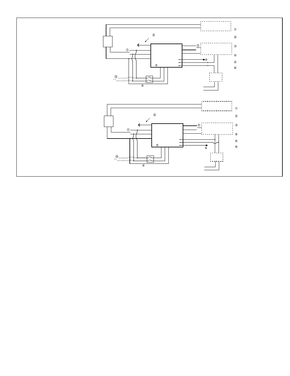
INVERTER - INTERRUPTIBLE WITH DIMMER BYPASS
120V
277V
LOCAL SWITCH
(IF PRESENT)
ALTERNATE
AC INPUT
INVERTER
WHT (NEUTRAL)
ORG (277V)
BLK (120V)
FLYING LEADS
GROUND
WIRE
YELLOW (277V)
VIOLET (120V)
GRAY (NEUTRAL)
GREEN
NORMAL CIRCUIT
EMERGENCY CIRCUIT
NORMAL
LIGHTING LOAD
DESIGNATED
EMERGENCY LOAD
INPUT
LEADS
VIOLET
BLK (120V
)
WHT (NEU)
OUTPUT
LEADS
BRANCH
CIRCUIT
OPERATES IN BOTH NORMAL AND
EMERGENCY MODES. CIRCUIT MUST BE
ISOLATED FROM NORMAL CIRCUITS.
BLU (NORMALLY OPEN)
RED (COMMON)
BRN (NORMALLY CLOSED)
DIMMER
CONTROL
DIMMING
RELAY
LEADS
PRIMARY
UNSWITCHED
INPUT
GRA
Y
VIOLE
T
GRA
Y
ORG (277V
)
The Dimming Relay contacts provide electrical continuity during normal power conditions allowing your dimming signal to
operate the luminaire in the desired, dimmed state. When the inverter transfers into the emergency mode, the dimming
relay contacts electrically open the 0-10 dimming reference signal forcing the luminaire to operate at full lumen output
regardless of dimmer setting.
SELECT PROPER VOLTAGE LEAD
AND CAP UNUSED LEAD.
GROUND WIRE - CONNECT FIXTURE SUPPLY
GROUND AND UNIT GROUND IN ACCORDANCE
WITH LOCAL AND NATIONAL CODES.
IF USING A SECONDARY AC INPUT,
SELECT PROPER VOLTAGE LEAD AND CAP
UNUSED LEAD.
USE A 277V RATED SWITCH IF
CONNECTING TO 277V INPUT.
FLYING LEADS - SELECT PROPER VOLTAGE
LEAD AND CAP UNUSED LEAD.
CAP UNUSED LEAD.
IIS-125 with Dimming Relay Wiring Connections
2. CONNECTING REMOTE EMERGENCY FIXTURES (DIAGRAMS 1 AND 2)
A. Connect remote emergency fixtures to the correct output leads. The color code is as follows: neutral is Gray, 120V
is Violet, and 277V is Yellow. All remote circuitry is to be wired in accordance with Article 700 of the National
Electric Code. Do not exceed the total rating of the
IIS-125. When making connections to the IIS-125, DO NOT
connect the Input Neutral (WHITE) to the Output Neutral (GRAY).
B. NORMALLY-OFF FIXTURES (only come on during power failure) - Connect the AC line input wire of the fixtures
to the appropriate output wires as above (120V or 277V). Connect the fixture Neutral input wire to the Neutral
output wire. Refer to
Diagrams 1 and 2.
C. NORMALLY-ON FIXTURES - Follow Step 2B above. Then select the proper voltage flying lead from the printed
circuit board (BLACK for 120V, ORANGE for 277V) and connect to the unswitched AC input line feeding the
transformer. Connect the Neutral (WHITE) flying lead coming from the printed circuit board to the unswitched AC
input neutral of the supply line feeding the input wires. Refer to
Diagrams 1 and 2.
D. FIXTURES ON LOCAL SWITCH (fixtures may be turned on and off locally, but will come on during power failure
regardless of switch position) - Follow Step 2B above. Connect the line side of the Switch to the unswitched
AC input line connected to the transformer. Connect the load side of the Switch to the proper voltage flying lead
from the printed circuit board (BLACK for 120V, ORANGE for 277V). Refer to
Diagrams 1 and 2. CAUTION: If
connected to 277 volt input, use a 277V rated switch. Failure to use the proper voltage switch may result
in switch failure, a shock hazard, an unsafe condition and equipment failure.
E. ALTERNATE FEED (all fixtures are supplied on normal from an alternate circuit) - Follow Step 2B above. Then extend
alternate AC input to the proper voltage flying leads from the printed circuit board (BLACK for 120V, ORANGE for
277V). If a local Switch is present, connect the alternate AC input to the Switch, then connect the proper voltage
flying leads from the printed circuit board to the load side of the Switch as in Step 2D. Refer to
Diagrams 1 and 2.
F.
DIMMING RELAY - The IIS-125 with Dimming Relay features a dimming relay for use with dimming applications.
The BLUE (Normally Open), RED (Common), BROWN (Normally Closed) leads are provided for connection to
the dimming circuit. Refer to the specifications of the dimming controls for proper wiring connections.
Consult
the
IIS
Application Notes for connecting the unit to specific lighting loads. Application Notes are
available on the internet or through Customer Service.
G. Connect the Fixture Supply Ground to the
IIS-125 Ground.
Diagram 1 - Dimmer Bypass
The Dimming Relay contacts provide
electrical continuity during normal
power conditions allowing your dim-
ming signal to operate the luminaire in
the desired, dimmed state. When the
inverter transfers into the emergency
mode, the dimming relay contacts
electrically open the 0-10 dimming
reference signal forcing the luminaire
to operate at full lumen output regard-
less of dimmer setting.
IIS_375_550_DR.EPS
INVERTER - INTERRUPTIBLE WITH EMERGENCY DIMMING SIGNAL
120V
277V
LOCAL SWITCH
(IF PRESENT)
ALTERNATE
AC INPUT
INVERTER
WHT (NEUTRAL)
ORG (277V)
BLK (120V)
FLYING LEADS
GROUND
WIRE
YELLOW (277V)
VIOLET (120V)
GRAY (NEUTRAL)
GREEN
NORMAL CIRCUIT
EMERGENCY CIRCUIT
NORMAL
LIGHTING LOAD
DESIGNATED
EMERGENCY LOAD
INPUT
LEADS
VIOLET
BLK (120V
)
WHT (NEU)
OUTPUT
LEADS
BRANCH
CIRCUIT
OPERATES IN BOTH NORMAL AND
EMERGENCY MODES. CIRCUIT MUST BE
ISOLATED FROM NORMAL CIRCUITS.
BLU (NORMALLY OPEN)
RED (COMMON)
BRN (NORMALLY CLOSED)
DIMMER
CONTROL
DIMMING
RELAY
LEADS
PRIMARY
UNSWITCHED
INPUT
GRA
Y
VIOLE
T
GRA
Y
ORG (277V
)
The Dimming Relay contacts are electrically open during normal power conditions allowing your dimming signal to operate the
luminaire in the desired, dimmed state. When the inverter transfers into the emergency mode, the dimming relay contacts electrically
short the 0-10 dimming reference signal forcing the luminaire to operate at a reduced lumen output setting based on the dimmable
driver being used. Verify operating results of the luminaire with the 0-10 volt reference signal shorted to assure the application and
mounting height produce code-compliant egress lighting.
SELECT PROPER VOLTAGE LEAD
AND CAP UNUSED LEAD.
GROUND WIRE - CONNECT FIXTURE SUPPLY
GROUND AND UNIT GROUND IN ACCORDANCE
WITH LOCAL AND NATIONAL CODES.
IF USING A SECONDARY AC INPUT,
SELECT PROPER VOLTAGE LEAD AND CAP
UNUSED LEAD.
USE A 277V RATED SWITCH IF
CONNECTING TO 277V INPUT.
FLYING LEADS - SELECT PROPER VOLTAGE
LEAD AND CAP UNUSED LEAD.
CAP UNUSED LEAD.
Diagram 2 - EM Dimming Signal
The Dimming Relay contacts are electri-
cally open during normal power conditions
allowing your dimming signal to operate
the luminaire in the desired, dimmed state.
When the inverter transfers into the emer-
gency mode, the dimming relay contacts
electrically short the 0-10 dimming refer-
ence signal forcing the luminaire to operate
at a reduced lumen output setting based
on the dimmable driver being used. Verify
operating results of the luminaire with the
0-10 volt reference signal shorted to as-
sure the application and mounting height
produce code-compliant egress lighting.