Installation instructions, Mounting the ets, Wiring – IOTA ETS User Manual
Page 2: Installing the led, Wiring the a.c. input
Page 2
INSTALLATION INSTRUCTIONS
CAUTION: Before installing, make certain the A.C. power is off.
1. MOUNTING THE ETS
Remove the ballast channel cover. Mount the
ETS in the ballast channel at least ½
″ away from the
A.C. ballast(s).
2. WIRING
Refer to the wiring diagrams on the back page for the appropriate wiring of lamp(s) and ballast. Install
in accordance with the National Electrical Code and local regulations. For additional wiring diagrams
consult Customer Service.
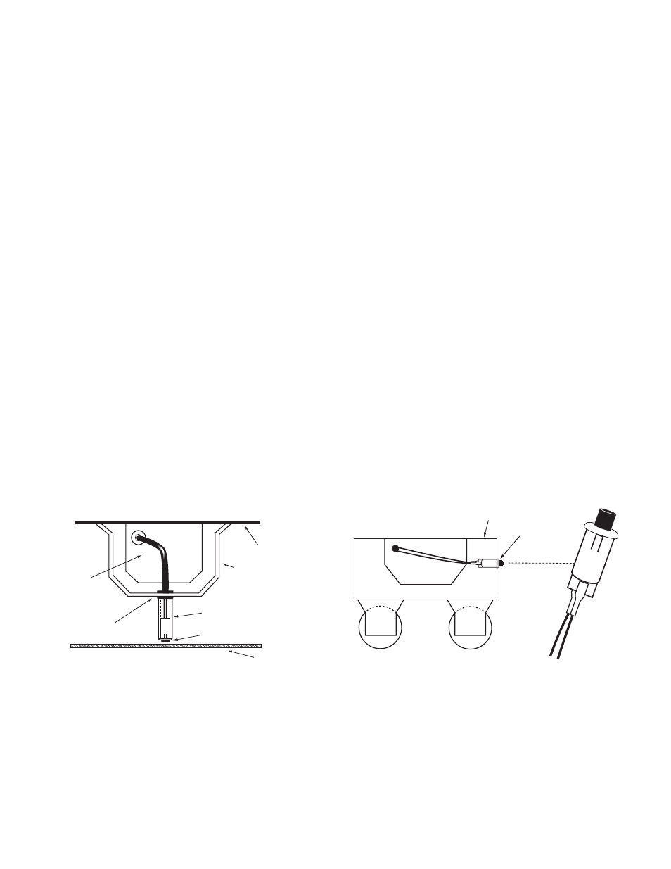
3. INSTALLING THE LED
Recessed Troffer Fixture – Select a convenient location with proper clearance in the ballast cover
and drill or punch a
7
/
8
″ hole (
1
/
2
″ knockout). Insert the
7
/
8
″ bushing into the hole. Push the plastic tube
through the bushing. Disconnect the leads from the
LED housing and route the leads down the plastic
tube. Reconnect the leads to the housing, observing the proper polarity (Yellow lead to red marked or
positive (+) red tab). Push the entire assembly back into the tube until the lens collar rests against the
plastic tube. The plastic tube should be adjusted so that the
LED is within ¼
″ of the fixture lens. The
LED must be visible after installation. Refer to Illustration 1.
Strip Fixture – Select a convenient location on the side of the fixture so the
LED can be seen after in-
stallation. Allow for proper clearance inside the fixture and drill or punch a ½
″ hole. Disconnect the leads
from the
LED housing. Push the LED housing into the ½
″ hole until it is firmly locked in place. Recon-
nect the leads, observing the proper polarity (Yellow lead to red marked or positive (+) red tab). Refer to
Illustration 2.
4.
WIRING THE A.C. INPUT
Refer to wiring diagrams on Page 4 for the proper wiring configuration of the
ETS. For wiring diagrams
not shown, consult Customer Service.
7/8" BUSHING
FIXTURE
BALLAST CHANNEL COVER
PLASTIC TUBE
CHARGE INDICATOR
LIGHT
FIXTURE LENS
Illustration 1 Recessed Troffer Fixture
FIXTURE
LPTS
+ RED
LEAD
WHITE/RED
LEAD
+ RED
Illustration 2
Strip Fixture
ETS
OBSERVE PROPER POLARITY
ETS
LED
LED
YELLOW/WHITE
or YELLOW/BLK
LEAD
YELLOW
LEAD