Installation instructions, Mounting the isd-420-em-b, Wiring – IOTA ISD-420-EM-B User Manual
Page 2: Wiring the a.c. input, Lamps operated
page 2
*The 6
″ violet leads provide the lamp selection option. The unit is shipped from the factory with the leads
disconnected and capped. When used with particular lamp types, violet leads should be connected to one anoth-
er. Refer to chart for lamp selection options.
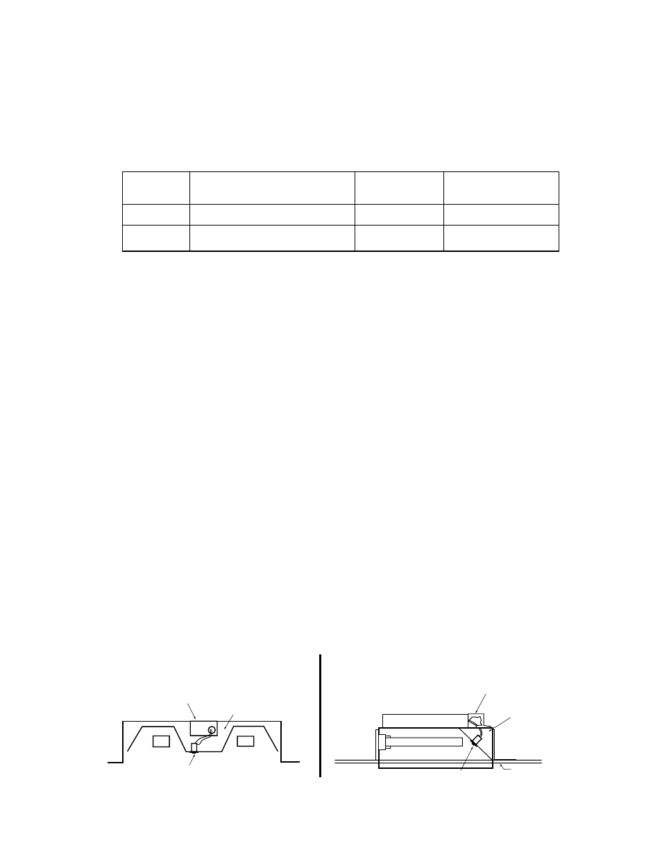
2. MOUNTINg THE ISD-420-EM-B
Mount
the
ISD-420-EM-B in the ballast channel or enclosed wireway so the wire leads are not exposed, at least
½
″
away from the A.C. ballast(s). Refer to Illustration 1. The
ISD-420-EM-B may also be mounted on top of the
fixture. The optional top mounting kit (Catalog No. TMK-80) may be ordered separately from Customer Service.
Refer to Illustration 2.
When battery packs are remote mounted, consult Customer Service for the maximum allowable distance between
the battery pack and the lamp.
3. WIRINg
Refer to the wiring diagrams on the back page for the appropriate wiring of lamp(s) and ballast. Install in accordance
with the National Electrical Code and local regulations. For additional wiring diagrams consult Customer Service.
4. INSTALLINg THE LIgHTED pUSH BUTTON TEST SWITCH (LpTS)
Select a convenient location on the side of the fixture so that the
LPTS can be seen after installation. Allow for
proper clearance and drill or punch a
7
/
8
″ (½″ knockout). push the LPTS housing into the ½″ hole. Connect the
leads, observing proper polarity (Red/Black or Red lead w/connector to positive (+) tab). The positive terminal will
be indicated by the red mark on the side of the LpTS switch. NOTE: For proper operation, use only the test acces-
sories provided with the unit. See Page 1 of the Instruction Manual.
5. WIRINg THE A.C. INpUT
A.
The
ISD-420-EM-B and A.C. ballast must be on the same branch circuit.
B.The
ISD-420-EM-B requires an unswitched A.C. power source of 110-277V 50/60HZ.
C.When the
ISD-420-EM-B is used with a switched fixture, the A.C. input to the ISD-420-EM-B must be connected
ahead of the fixture switch. Refer to Illustration 3 for switched and unswitched fixture wiring diagrams.
For 208VAC applications, consult Customer Service.
INSTALLATION INSTRUCTIONS
CAUTION: Before installing, make certain the A.C. power is off and the
ISD-420-EM-B unit connector is disconnected.
1. LAMpS OpERATED
Refer to the chart below for the type of lamp to be operated in the emergency mode.If you have any questions regard-
ing specific lamps, contact Customer Service.
Illustration 1: Twin Lamp Fixture
INSURE WIRING IS IN ACCORDANCE WITH THE NATIONAL ELECTRICAL CODE AND LOCAL REGULATIONS.
Illustration 2: Top Mount Option
LPTS
A.C. BALLAST
CHANNEL
CEILING TILE
A.C. BALLAST
COMPARTMENT
LPTS
TMK-80
ISD-420-EM-B
ISD-420-EM-B
OPTION
LAMP TYPE
EMERGENCY
OPERATION
*VIOLET LEADS
1
2
13W - 32W Compact
42W - 57W Compact
One Lamp
One Lamp
Connected
Disconnected