Installation instructions, Engineering considerations, Lamps operated – IOTA I-42-L User Manual
Page 2: Mounting the i-42-l and battery, Conditions of acceptability, Illustration 1 illustration 2 - tbts, Page 2
Page 2
+ RED
LEAD
WHITE
LEAD
Mounting
Barrier
Leave space
between boards
Use – For use only in complete equipment or final applications where the acceptability of the combination is deter-
mined by Underwriters Laboratories, Inc.
These components have been judged on the basis of the required spacings in the Standard for Emergency Lighting
and Power Equipment UL 924, Sec. 29, which covers the end use product for which the component was designed.
CONDITIONS OF ACCEPTABILITy
1. Installed in a suitable ultimate enclosure.
2. Used with marked electrical ratings.
3. Provide with proper spacing between live parts and enclosure and/or adjacent devices.
4. Factory wired only (terminations not suitable for field wiring).
5. Temperature tests may have to be repeated where battery temperature exceeds 50° C.
6. Mounted within the end-use product such that the battery is secured and the test switch operates properly
when the end product is fully assembled.
7. End-use products employing one or more of these devices are to be marked in accordance with the Standard
for Emergency Lighting and Power Equipment, UL 924.
INSTALLATION INSTRUCTIONS
CAUTION: Before installing, make certain the A.C. power is off and the I-42-L unit connector is disconnected.
1. LAMPS OPERATED
Refer to the chart below for the type of lamp(s) operated and the number of lamps to be operated in the emergency mode.
If you have any questions regarding specific lamps, contact customer service.
INSURE WIRING IS IN ACCORDANCE WITH THE NATIONAL ELECTRICAL CODE AND LOCAL REGULATIONS.
The
6
″ violet leads provide the lamp selection option. The unit is shipped from the factory with the leads
disconnected and capped. When used with particular lamp types, violet leads should be connected to one anoth-
er. Refer to chart for lamp selection options.
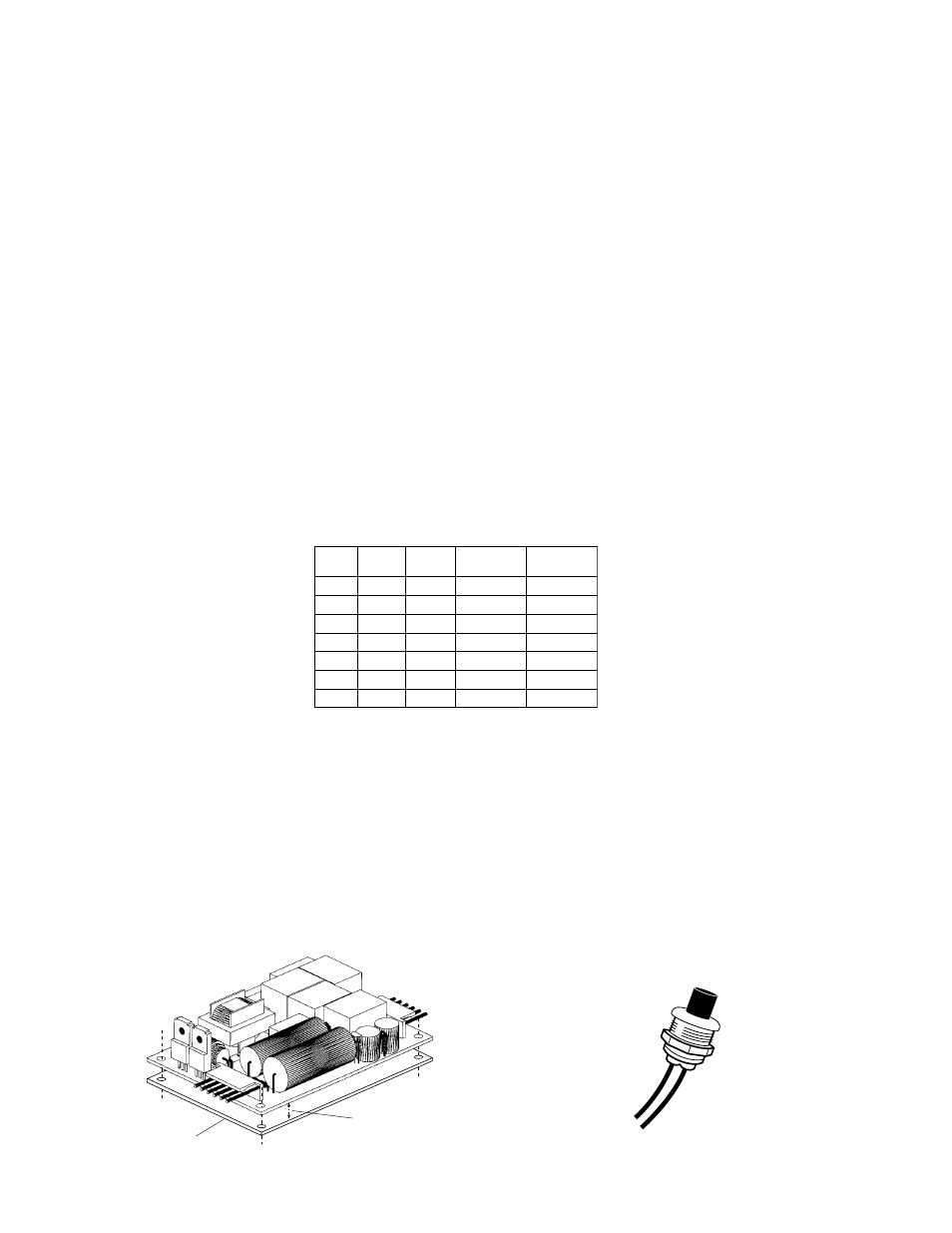
2. MOUNTINg ThE I-42-L AND BATTERy
Mount
the
I-42-L in the ballast channel or enclosed wireway so the wire leads are not exposed, at least
1
/
2
″
away
from the A.C. ballast(s). Mount the
I-42-L using the mounting holes provided. The insulating barrier should be
mounted against the fixture wall. Then the main circuit board can be mounted leaving a space between the board
and the mounting barrier as shown in Illustration 1. The circuit board should be placed so that no live parts are ac-
cessible during routine maintenance or relamping.
The battery should be at least
1
/
2
″ from the A.C. ballast and other heat sources. Since heat rises, try to mount the
battery as low as possible.
CAUTION
– Connect the battery to the unit before applying A.C. power.
N
O
I
T
P
O
P
M
A
L
E
P
y
T
y
C
N
E
g
R
E
M
E
N
O
I
T
A
R
E
P
O
T
E
L
O
I
V
S
D
A
E
L
1
2
3
4
10W-18W
26W-42W
18W
One Lamp
One Lamp
Two Lamp
Two Lamp
Compact
Compact
Compact
Compact
Connected
Disconnected
Connected
Disconnected
10W-13W
5
6
7
18W
24W
36W
Long
Compact
Long
Compact
Long
Compact
One Lamp
One Lamp
One Lamp
Connected
Disconnected
Disconnected
ENGINEERING CONSIDERATIONS
Illustration 1
Illustration 2 - TBTS
OBSERVE PROPER
POLARITy