Installation instructions, Lamps operated, Mounting the i-42-em-b – IOTA I-42-EM-B User Manual
Page 2: Installing the threaded body test switch (tbts), Wiring, Labels, Illustration 1 - twin lamp fixture, Illustration 2 - top mounting with tmk-80 option
Page 2
INSTALLATION INSTRUCTIONS
CAUTION: Before installing, make certain the A.C. power is off and the
I-42-EM-B unit connector is disconnected.
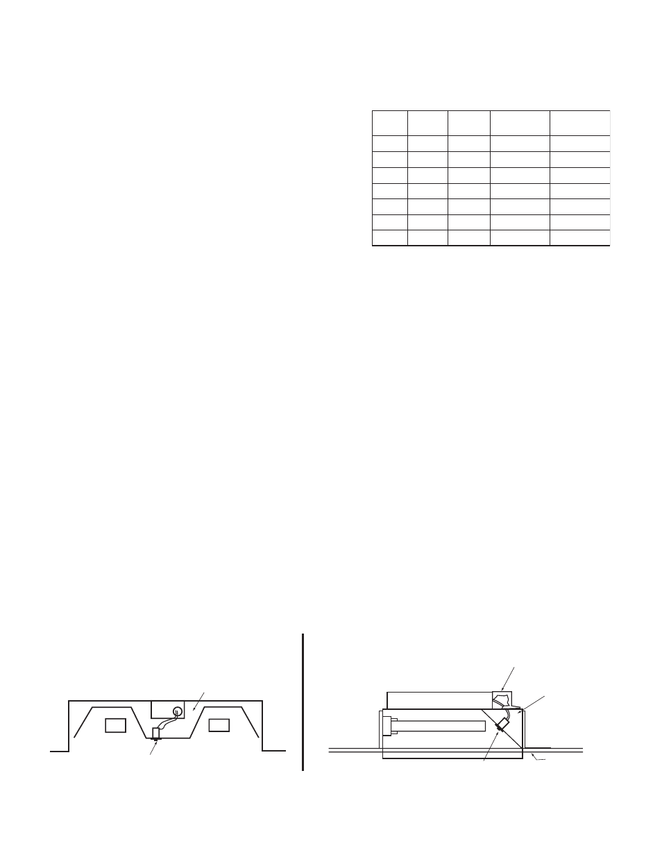
Illustration 1 - Twin Lamp Fixture
INSURE WIRING IS IN ACCORDANCE WITH THE NATIONAL ELECTRICAL CODE AND LOCAL REGULATIONS.
1. LAMPS OPERATED
Refer to the chart for the type of lamp(s) operated and the number
of lamps to be operated in the emergency mode.
If you have any questions regarding specific lamps, contact
Customer Service.
The
6
″ violet leads provide the lamp selection option. The unit
is shipped from the factory with the leads disconnected and
capped. When used with particular lamp types, violet leads
should be connected to one another. Refer to the chart for
lamp selection options.
LPTS
A.C. BALLAST
CHANNEL
CEILING TILE
A.C. BALLAST
COMPARTMENT
LPTS
TMK-80
Illustration 2 - Top Mounting with TMK-80 Option
TBTS
TBTS
N
O
I
T
P
O
P
M
A
L
E
P
Y
T
Y
C
N
E
G
R
E
M
E
N
O
I
T
A
R
E
P
O
T
E
L
O
I
V
S
D
A
E
L
1
2
3
4
10W-18W
26W-42W
18W
One Lamp
One Lamp
Two Lamp
Two Lamp
Compact
Compact
Compact
Compact
Connected
Disconnected
Connected
Disconnected
10W-13W
5
6
7
18W
24W
36W
Long
Compact
Long
Compact
Long
Compact
One Lamp
One Lamp
One Lamp
Connected
Disconnected
Disconnected
2. MOUNTING THE I-42-EM-B
Mount
the
I-42-EM-B in the ballast channel or enclosed wireway so the wire leads are not exposed, at least ½
″
away from the A.C. ballast(s). Refer to Illustration 1. For mounting the
I-42-EM-B on top of the fixture, use the
optional TMK-80 mounting accessory for covering the wires that enter the fixture. Refer to Illustration 2.
When battery packs are remote mounted, consult Customer Service for the maximum allowable distance between
the battery pack and the lamp(s).
3. INSTALLING THE THREADED BODY TEST SWITCH (TBTS)
Select a convenient location on the side of the fixture so that the
TBTS can be seen after installation. Allow for
proper clearance and drill or punch a ½
″ hole. Remove the nut from the TBTS. Push the TBTS housing into the
½
″ hole and secure with the nut. Connect the LED wires from the unit to the TBTS (Red/Black or Red w/tag to
Red, and White/Red to White).
4. WIRING
A. When the
I-42-EM-B is installed on the same branch circuit, refer to Illustration 3, Figures A and B for
input wiring. When installed on separate branch circuits, refer to Illustration 3, Figures C and D for input wiring.
Per NEC, the
I-42-EM-B and A.C. ballast must be on the same panel board.
B. The
I-42-EM-B requires an unswitched A.C. power source of either 120 or 277 volts; therefore, when
used with switched fixtures, the
I-42-EM-B input must be wired ahead of the switch. Refer to Illustration 3
for switched and unswitched fixture wiring diagrams.
C. Refer to the wiring diagrams on the back page for the proper wiring. For wiring diagrams of ballasts not shown,
consult our Customer Service.
5. LABELS
Attach the appropriate labels adjacent to the
TBTS. Annotate Re-lamping label for lamp type and wattage. The
Caution and the Re-lamping labels must be on the fixture in a readily visible location to anyone attempting to ser-
vice the fixture.