Installation instructions, Mounting the isl-540, Wiring – IOTA ISL-540-35W User Manual
Page 2: Installing the threaded body test switch (tbts), Wiring the a.c. input
Page 2
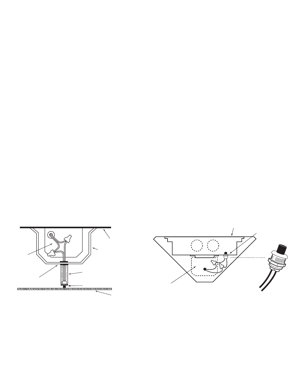
7/8" BUSHING
FIXTURE
BALLAST CHANNEL COVER
PLASTIC TUBE
TBTS
FIXTURE LENS
INSTALLATION INSTRUCTIONS
CAUTION: Before installing, make certain the A.C. power is off and the
ISL-540 unit connector is disconnected.
1. MOUNTING THE ISL-540
Remove the ballast channel cover. Mount the
ISL-540 in the ballast channel at least
1
/
2
″ away from the A.C.
ballast(s).
When battery packs are remote mounted, consult Customer Service for the maximum allowable distance between
the battery pack and the lamp.
2. WIRING
Refer to the wiring diagrams on the back page for the appropriate wiring of lamp(s) and ballast. Install in accordance
with the National Electrical Code and local regulations. For additional wiring diagrams consult Customer Service.
3. INSTALLING THE THREADED BODY TEST SWITCH (TBTS)
Recessed Troffer Fixture – Select a convenient location with proper clearance in the ballast cover and drill or
punch a
7
/
8
″ hole (
1
/
2
″ knockout). Insert the
7
/
8
″ bushing into the hole. Push the plastic tube through the bushing.
Route the leads of the
TBTS through the plastic tube. Connect the LED wires from the unit to the TBTS (Red/
Black or Red w/tag to Red, White/Red to White). Push the entire assembly back into the tube until the lens collar
rests against the plastic tube. The plastic tube should be adjusted so that the
TBTS is within ¼
″ of the fixture lens.
The
TBTS must be visible after installation. Refer to Illustration 1.
Linear Fixture – Select a convenient location on the fixture so the
TBTS can be seen after installation. Allow for
proper clearance inside the fixture and drill or punch a
1
/
2
″ hole. Remove the nut from the TBTS. Push the TBTS
housing into the
1
/
2
″ hole and secure with the nut. Connect the LED wires from the unit to the TBTS (Red/Black or
Red w/tag to Red, White/Red to White). Refer to Illustration 2.
4. WIRING THE A.C. INPUT
A. The
ISL-540 and A.C. ballast must be on the same branch circuit.
B. The
ISL-540 requires an unswitched A.C. power source of either 120 or 277 volts. Select the proper voltage
lead and cap the unused lead.
C. When the
ISL-540 is used with a switched fixture, the A.C. input to the ISL-540 must be connected ahead of
the fixture switch. Refer to Illustration 3 for switched and unswitched fixture wiring diagrams.
Illustration 1 Recessed Troffer Fixture
Illustration 2 Linear Fixture
ISL-540
OBSERVE PROPER POLARITY
+ RED
LEAD
WHITE
LEAD
FIXTURE
TBTS
ISL-540