Installation instructions, Mounting the i-162, Wiring – IOTA I-162 User Manual
Page 2: Installing the charge indicator, Installing the test switch, Wiring the a.c. input, Illustration 1 recessed troffer fixture
Page 2
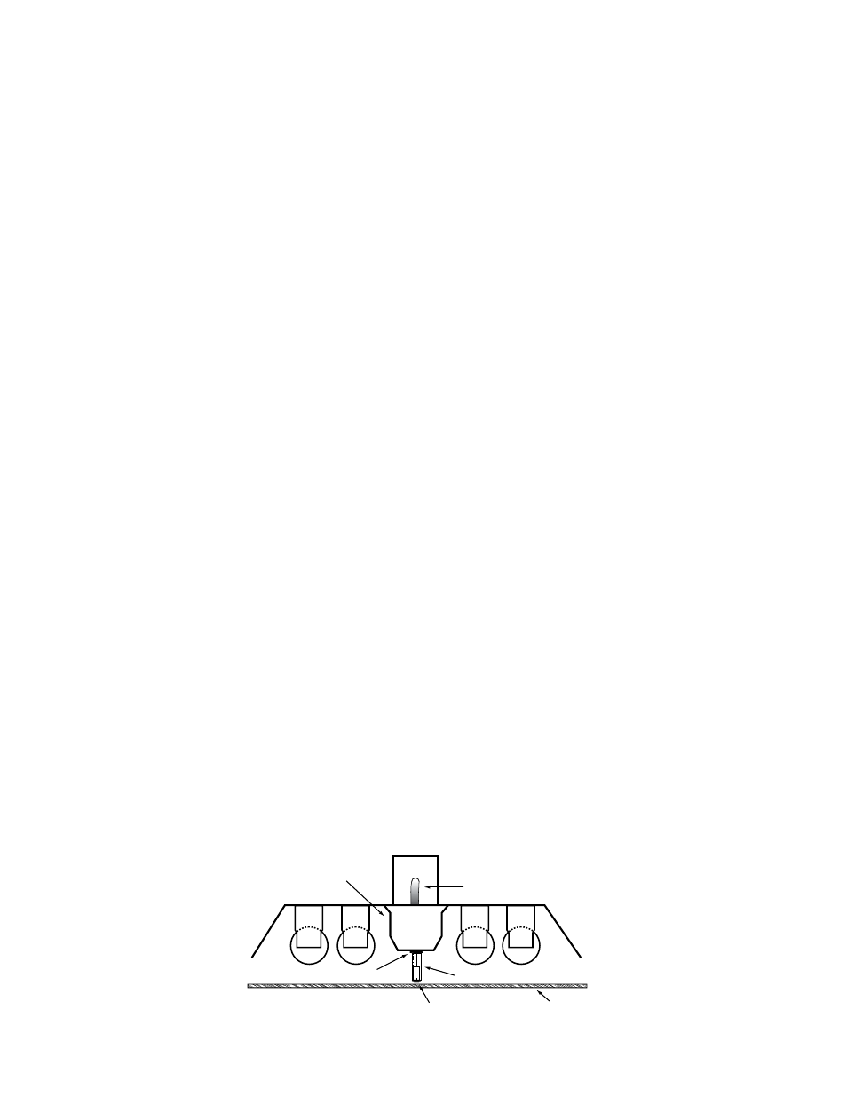
7/8" BUSHING
PLASTIC TUBE
CHARGE INDICATOR LAMP
BALLAST CHANNEL
COVER
FLEX CONDUIT
FIXTURE LENS
INSTALLATION INSTRUCTIONS
CAUTION: Before installing, make certain the A.C. power is off and the I-162 unit connector is disconnected.
1. mOUNTINg ThE I-162
Remove the ballast channel cover. mount the
I-162 on the fixture top in a position that does not interfere with the existing A.C.
ballast or any other hardware. Extend the flex conduit to a convenient location on top of the fixture and punch a
7
/
8
″ hole. Feed the
wires and flex connector down through the hole in the fixture and secure in place with the flex connector nut. An optional T-bar
mounting kit is available to mount the
I-162 above the ceiling tile adjacent to the emergency fixture. To order the optional T-bar
mounting kit (part number TBmK-160) contact Customer Service.
When battery packs are remote mounted, consult Customer Service for the maximum allowable distance between the battery
pack and lamp.
CAUTION: Properly secure the I-162 in the ceiling grid to insure compliance with local, state, and federal guidelines re-
garding ceiling mounted equipment.
2. WIRINg
Refer to the wiring diagrams on the back page for the appropriate wiring of lamps and ballast. Install in accordance with the Na-
tional Electrical Code and local regulations. For additional wiring diagrams consult Customer Service.
3. INSTALLINg ThE ChARgE INDICATOR
Recessed Troffer Fixture – Select a convenient location with proper clearance in the ballast cover and drill or punch a
7
/
8
″ hole
(
1
/
2
″ knockout). Insert the
7
/
8
″ bushing into the hole. Push the plastic tube through the bushing. Disconnect the leads from the LED
housing and route the leads down the plastic tube. Reconnect the leads to the housing, observing the proper polarity (Red/Black
or Red lead w/connector to positive (+) red tab). Push the entire assembly back into the tube until the lens collar rests against the
plastic tube. The plastic tube should be adjusted so that the
Charge Indicator is within ¼
″ of the fixture lens. The Charge Indica-
tor must be visible after installation. Refer to Illustration 1.
Ceiling-Mounted Downlight Fixture – Select a convenient location on the side of the fixture so the
Charge Indicator can be seen
after installation. Allow for proper clearance inside the fixture and drill or punch a
1
/
2
″ hole. Disconnect the leads from the LED
housing. Push the
LED housing into the
1
/
2
″ hole until it is firmly locked in place. Reconnect the leads, observing the proper polarity
(Red/Black or Red lead w/connector to positive (+) red tab). For remote mounting the charge indicator and test switch, the optional
RTK accessory kit can be ordered.
Note: For proper operation, use only the accessory components provided with the unit. See Page 1 of the Instruction Manual.
4. INSTALLINg ThE TEST SWITCh
The test switch should be mounted on the ballast channel cover of a recessed troffer, or on the side of a strip fixture, preferably
adjacent to the charge indicator. Drill or punch a
1
/
2
″ mounting hole. Refer to Illustration 2.
5. WIRINg ThE A.C. INPUT
A. The
I-162 requires an unswitched A.C. power source of either 120 or 277 volts. Select the proper voltage lead and cap the
unused lead.
B.
When
the
I-162 is used with a switched fixture, the A.C. input to the I-162 must be connected ahead of the fixture switch.
Refer to Illustration 2 for switched and unswitched fixture wiring diagrams.
C.
When installed on separate branch circuits, refer to Illustration 2, Figures C and D for input wiring. Per NEC, the
I-162 and
A.C. ballast must be on the same panel board.
Illustration 1 Recessed Troffer Fixture
I-162